> Does anyone have the O/S, Applications, and Diagnostice disks
I'm trying to find this as well.
Just picked up the manual set. It should be on bitsavers soon.
Kevin Schoedel said he had a copy as of Apr,2000
> On 2000/04/28 at 9:18pm -0500, Joe <rigdonj at intellistar.net>
wrote:
>> I picked up a second FLuke 1722 today. This one does have the
keyboard
>>(at last)! But I still haven't found the operating system
software for it.
>>Can anyone help? It uses Fluke's F-DOS. I'd also like to find a
manual
>>for it.
>
> I a Fluke 1720A with F-DOS. If there are grounds to believe that
the same
> software would work, I can try to do something about copying or
archiving
> the disks soon(er than I otherwise would). I might have multiple
copies
> already, though I seem to recall that only one was reliably
readable. I
> certainly do have multiple copies of the 1720A manuals.
Maybe this will be of interest to someone here:
http://newjersey.craigslist.org/sof/138336632.html
- Expert knowledge of VAX VMS operating system and VAX System administration.
and more....
Cheers,
Bryan
I am finally starting to clean up stuff ... again, and most of the stuff
is being listed on VCM, http://www.vintagecomputermarketplace.com/. If
you feel the prices are way too low, let me know :). And ditto if you
think they are too high.
Mostly, I am culling back my collection of most things after about 1984
or so. I would love to have the time to play with the S-100 systems, get
the Polymorphic and Lobo Drives stuff cataloged and working, etc. There
are probably some things that got lost in email from the VCM over the
past several months, so if I've forgotten or not responded to something
purchased there several months ago, please let me know. I tend to forget
to change some of the posts to "sold."
I have 2 to get rid of, with keyboard and external drive units. Pickup only
(or you arrange for packing and shipping), North (and I mean north, none of
that Newark/Edison stuff) New Jersey.
I'm looking for a Model I, an MC-10, a DT-100, a PT-210, Model 2000, and
just about everything else tandy related.
Make a swap offer.
Kelly
Wow Philippe,
looking at your website, I got an impressive insight on the work you did to get this PDP 8/L up and running again.
Keep on saving and repairing stuff!
Regards,
Pierre
"General Discussion: On-Topic Posts Only" <cctech at classiccmp.org> schrieb am 05.03.06 12:53:14:
>
> Dear Tim,
>
> It is very hard to answer your question. I also spent hours fixing my
> pdp-8/L, in which almost all circuits had to be repaired. It took me two
> years. The only way : use a logic probe and have a set a spare flipchips
> which you know are OK. I created a system to test the flipchips using a
> digital acquisition card on a PC (see www.sonnet.be). Collect all possible
> schematics, study them, have a confortable seat, stay calm and systematic
> and use a card extender to have better access to all the lines.
> Good luck,
>
> Philippe
>
> ----- Original Message -----
> From: "Tim" <tradde at excite.com>
> To: <cctalk at classiccmp.org>
> Sent: Saturday, February 18, 2006 11:30 PM
> Subject: My pdp-8i problem
>
>
> >
> > I was hoping someone on this list might have some input on this. I have
> > also posted this to alt.sys.pdp8. I have a pdp-8i with a memory problem.
> > Here is the post from alt.sys.pdp8:
> >
> > Quite some time back while scoping out a problem I shorted a pin in my
> > 8i backplane and lost memory control. Since that time Vince and I have
> > been trying to figure out where the problem is to fix it. I don't know
> > what pin I shorted as at the time I did not realize
> > I had damaged anything. The +5v breaker tripped though.
> >
> > The problem is I can not deposit or read back any memory locations.
> > The MB is displayed correctly on a deposit. Scoping signal has shown me a
> > very odd signal on B FIELD 0 (1) when the machine is in run mode. It has
> > a wave form on it rather than just a normal
> > voltage. The oddest thing is the high point of the wave goes up to +6v
> > with a bit of the beginning of the top portion going above +6v. To me
> > this should not be. How can I get
> > +6v from a system that is using +5v as it's input voltage? We have
> > some theories but nothing concrete as yet. The other thing is if I remove
> > all 3 G228s (A36, B36, B37) the
> > signal goes away. I do not have parity memory so nothing is in A37.
> >
> > We believe there is a bad ground somewhere, but I have not been able to
> > determine where. I do not have a wiring list so I may have to trace some
> > signals manually. I think I have to find all the places the B30L1 (B FIELD
> > 0(1)) goes to.
> >
> > Any ideas or suggestions from anyone? This has been bugging me for a
> > long time. I look at it for awhile, and then put it down for awhile. It's
> > also not easy to look at this in the location it is in. It's too low to
> > kneel and really be comfortable. Too high to lay on my stomach. :)
> >
> > Thanks for any input on this. I should say that part of the system
> > still works. Examining or depositing memory while it does not appear to
> > load/store the data increments the PC
> > as it should. I can sort of run, which was my original problem. It
> > runs but stays at location zero. It is not an interrupt causing this. So
> > the front panel is mostly operational
> > so at least some of the machine is still working. I just have to find
> > the problem with the memory.
> >
> > I know most people on this list do not have a pdp-8i, nor may know
> > much if anything about them. Any suggestion will be taken and looked
> > into if it seems to have hope of leading to a solution. Also I will
> > answer any questions people have to help describe the problem more or
> > give more details into what Vince and I have looked at.
> >
> > Tim Radde
> >
> > _______________________________________________
> > Join Excite! - http://www.excite.com
> > The most personalized portal on the Web!
> >
> >
> >
>
______________________________________________________________________
XXL-Speicher, PC-Virenschutz, Spartarife & mehr: Nur im WEB.DE Club!
Jetzt gratis testen! http://freemail.web.de/home/landingpad/?mc=021130
Hi All,
I seem to remember that when I used a VT320 under VMS
and EVE/TPU (or at least one of the DEC editors), there was
status information on line 25 for the user. I think the file name
under edit was displayed and perhaps even the line number and
column number, although I really am doubtful about the latter.
BUT I do seem to remember the file name being available on
line 25. Am I correct? Please help! The VT220 was not able
to support line 25 as far as I know, and certainly the VT100
was not able. What about the VT410 and VT520 terminals?
Sincerely yours,
Jerome Fine
--
If you attempted to send a reply and the original e-mail
address has been discontinued due a high volume of junk
e-mail, then the semi-permanent e-mail address can be
obtained by replacing the four characters preceding the
'at' with the four digits of the current year.
All:
I recently received from a friend a Televideo 910 terminal that
seems to have been drop-kicked off of the back of the mail truck. It was
dropped keyboard first, so the entire front broke off. So far, gluing the
case isn't working well, and I'm not optimistic about the ultimate success.
So, I'm looking for someone with a bad terminal with a good case so I can
make a Frankenstein terminal.
Please contact me off-list. Thanks.
Rich
Rich Cini
Collector of classic computers
Build Master for the Altair32 Emulation Project
Web site: <http://highgate.comm.sfu.ca/~rcini/classiccmp/>
http://highgate.comm.sfu.ca/~rcini/classiccmp/
/************************************************************/
I'm not an expert
>in the MCP O/S so have been in lurkmode on this for a
>longnow while.
>From what I've been able to tell, the thing executes a superset of the old
1107 instruction set.
---
Wrong side of the merger. MCP was from the Burroughs side. Descendent of
the 5500 family.
Clearpath/OS2000 are the ones-compliment 11xx family.
what a boring magazine. It really is a dull read. Not
sure why I want to add to my accumulation (have 16
between 1/85 - 12/87). But alas I am. Let me know even
if yer just looking for an article or two.
__________________________________________________
Do You Yahoo!?
Tired of spam? Yahoo! Mail has the best spam protection around
http://mail.yahoo.com
the 9801 was not an all in one though. I cant imagine
myself confusing NEC and NCR actually, just that I was
somewhat familiar with their PC4s, and it seemed a tad
different IIRC. It could have been the Decision Mate,
which doesnt look any different, and would also boot
to a cpm a> prompt (Im thinking so anyway). The thing
just somehow looked different...(I was hoping some
nerd who also used to shop their might subscribe to
this list).
--- cctech-bounces at classiccmp.org <Tim at Rikers.org>
wrote:
> Chris M wrote:
> > the talk of a peculiar USR pc made me remember
this.
> > There used to be a (primarily) electronic junk
store
> > in LI called Eldies (Edlies?) on Hempstead Tnpk in
> > Levittown I guess. Sitting there one day was an
all in
> > one, IIRC, NCR unit that booted up to an a:>
prompt.
> > It struck me as a weirdish dos semi compatible. It
> > didnt strike me as a PC4 or the nearly identical
> > Decision Mate (cpm). Pretty sure it was NCR, but
eh
> > maybe it was NEC (definately NOT an APC, not quite
> > that big and heavy). Anyone have a clue?
>
> The Japanese NEC PC-9800 series booted with A: as
the boot drive even if
> it booted off a hard disk. the floppies would become
the next drives.
>
> Was the text in japanese?
>
> I did software development on some of these models
back around 1990. All
> the M$ tools were available for them, but only from
Japanese dealers and
> only in Japanese.
>
> --
> Tim Riker - http://Rikers.org/ - TimR at Debian.org
> Embedded Linux Technologist - http://eLinux.org/
> BZFlag maintainer - http://BZFlag.org/ - for fun!
__________________________________________________
Do You Yahoo!?
Tired of spam? Yahoo! Mail has the best spam protection around
http://mail.yahoo.com
Hi,
Did you every find Trainer.zip? If not I have attached it.
Cleve
__________________________________________________
Do You Yahoo!?
Tired of spam? Yahoo! Mail has the best spam protection around
http://mail.yahoo.com
> made. One other thing that might be of interest : The 34 pin connector on
> the back of the TF20 is not some kind of parallel host interface. It's
> exactly what you'd expect a 34 pin connector on a disk controller to be
> -- namely a SA400-compatible disk drive bus. The hardware can handle up
>
If the processor board is left out of the TF-20 you could use the drives
as extra drives on a QX-10. Some more info on the TF-20 and HX-20 Disk
basic can be learned from the User manual:
http://electrickery.xs4all.nl/comp/tf20/doc/tf-20_manual.pdf or
http://oldcomputers.dyndns.org/public/pub/rechner/epson/~fjkraan/comp/tf20/….
The CP/M like OS in the TF-20 probably doesn't support the extra drives
as the official way to connect more drives is daisy chaining another
TF-20 to the first one.
Fred Jan
On 05/03/06, Zane H. Healy <healyzh at aracnet.com> wrote:
>
> At 12:31 PM +0000 3/5/06, Philip Pemberton wrote:
> >In message <20060304205928.017C8BA48B5 at mini-me.trailing-edge.com>
> > shoppa_classiccmp at trailing-edge.com (Tim Shoppa) wrote:
>
> >Tom Swift? Never heard of 'em... It's either way before my time, or one
> of
> >the many things that never managed to get across the Atlantic...
>
> It probably never made it across the Atlantic.
They did, I remember reading several of them from our primary school library
in the mid 70's, I suppose I would have been 8 or 9. All I can remember now
is he had a very cool submarine/helicopter contraption that could fly at
humoungous speed and that the style, with hindsight, was E.E Smith gung-ho
for a junior audience.
--
Pete Edwards
"Prediction is very difficult, especially if it's about the future" - Niels
Bohr
Philip Pemberton <philpem at dsl.pipex.com> wrote:
> Tom Swift? Never heard of 'em... It's either way before my time, or one of
> the many things that never managed to get across the Atlantic...
actually they did, look at
http://www.tomswift.info/homepage/british.html
for the British version of the Tom Swift books (published by Collins).
**vp
Dear all,
Trying to identify a box of HP cables. There are two types.
One has a 50-pin centronics-style connector at one end, and a 50-pin
Winchester MRAC rack-and-panel connector at the other. The other
type has Winchesters at both ends. They're about 4-5 feet in length.
All seem to have an metal band with the number "5060 2310". Some have
HP "inspected by 7452" cards tied to them, dated 6/69. A couple have
factory vinyl or poly bags.
Anyone know what devices these connect?
Thanks,
De
On my wandering around, I found the following claims on the Unisys
"history" web page (http://www.unisys.com/about__unisys/history/index.htm):
"1993 Unisys introduces 2200/500, the first mainframe based on
complementary metal oxide semiconductor (CMOS) technology."
Wasn't the ETA-10 CMOS-based? (Not to mention the whole subject of
"What's a mainframe?")
"1989 Unisys introduces Micro A, the first desktop, single-chip mainframe."
I don't know what to make of that claim. What's a mainframe. From what I
can gather, the Micro A was pretty much a plug-in coprocessor PCB in an
otherwise x86 box that booted OS/2.
Comments? Anyone on the list a Blue Bell veteran who can give the real
scoop on the Micro A?
Cheers,
Chuck
a vintage cohort has supplied me with a stack of
floppies for this unit. With all deference to Dave and
his software, would ImageDisk be the best tool for the
job? Stated another way, would these disks require any
special handling? Theyre quad density 800k, or single
sided 400k (methinks). Possibly readable by DOS (a
guess, and not a crazy one if youre familiar with the
machine), in which case my concerns are unfounded.
__________________________________________________
Do You Yahoo!?
Tired of spam? Yahoo! Mail has the best spam protection around
http://mail.yahoo.com
"Jerome H. Fine" <jhfinedp3k at compsys.to> wrote:
> Hi All,
>
> I have noticed what may be an interesting result when I use the
> PDP-11 Integer Divide Instruction "Div". Since I have noticed
> at least one individual who worked on the microcode for the
> PDP-11, perhaps there is an explicit "Yes / No" answer to my
> question:
Since this actually have nothing to do with the microcode, and actually
is nothing specific with the PDP-11 DIV instruction, just about anyone
should be able to answer definitely.
> If I divide 196612 by 3 - i.e. "Div (R2),R0" where R0 = 3, R1 = 4,
(R2) = 3
> the result (in addition to the condition bits) is R0 = 1, R1 = 1 which is
> exactly correct if the quotient is regarded as a 32 bit result with
R0 being
> the low order 16 bits of that result and the high order 32 bits are
somewhere
> else - probably inaccessible as far as programming is concerned, but
easily
> obtained by:
> Mov R1-(SP) ; Save low order 16 bits of dividend
> Mov R0,R1 ; Divide high order 16 bits
> Clr R0 ; of dividend
> Div (R2),R0 ; by the divisor
> Mov R0,R3 ; Save high order 16 bits of quotient
> Mov R1,R0 ; Divide the remainder
> Mov (SP)+,R1 ; of the dividend
> Div (R2),R0 ; by the divisor
> i.e. R3 now contains the high order 16 bits of the 32 bit quotient
> with R0 holding the low order 16 bits of the 32 bit quotient
What you have implemented here, as well as described, is the exact way
you should have been taught how to do division on paper in elementary
school.
Yes, that algorithm is valid, and can be extended to arbitrary sizes, as
long as you remember the full method.
> Can anyone confirm what I have found in practice?
Certainly. It's basic math, the way it's taught in elementary school.
That was atleast the first way I was taught how do do divides on big
numbers on paper.
> Even better would be a method of retrieving the high
> order 16 bits of the quotient in a manner which takes
> fewer instructions and without a second divide instruction!
I doubt you'll find it.
Johnny
--
Johnny Billquist || "I'm on a bus
|| on a psychedelic trip
email: bqt at update.uu.se || Reading murder books
pdp is alive! || tryin' to stay hip" - B. Idol
a gentleman named Steve Thompson has a PDP 11/53 "box" available for
pickup in Stafford/Fredericksburg Virginia area (it is just the
system cabinet - no peripherals, no manuals). He will have to
dumpster it if no one wants it (he would hate to do that, but...). He
needs to get it taken care of by the end of this month. I know
nothing about the system, so please call him at 540-659-9906 for any
additional info (he is not a computer collector as such so don't
expect a lot of detailed info).
Keep in mind that the phone number is Eastern Standard time, so
please call before 9PM his time in the evenings (that's no later than
6PM for those of us that live on the West coast).
Thanks.
best regards, Steve Thatcher
SD320, SD321 drive dismantling
-------------------------------
Remove the logic board :
Undo the 4 screws fixing the logic board. The rear left is a long machine
screw, rear right a short machine screw, centre right and front centre are
(short) self-tapping screws. Lift the logic board to disconnect the 3 pin
connector at front left (index/write protect sensors), 10 pin
(positioner) and 3 pin (spindle motor) connectors at rear. Turn logic
board over towards right side of the drive. Free the head cables from the
clamps on the logic PCB, unplug the head connector. Set the logic board
aside.
On SD320 (with head load solenoid), dismantle the head load mechanism :
Remove the screw and washer on top of the head load solenoid. Loosen the
screw fro the rear bearing of the head load flap (this screw is on the
left side of the drive chassis) until the bearing can be turned away from
the pivot pin. Free the hard load flap from its front bearing, remove it,
note how the compression spring fits over a peg on the base of the linear
positioner. Remove the conical spring from the top of the head load
solenoid, remove the solenoid armature. Remove the screw and bearing
(loosened earlier). Remove the screw holding the head load solenoid to
the chassis, lift out the solenoid and 'stick' it to the linear
positioner magnet. When reassembling this section, note that the screw on
top of the solenoid should not be fully tightened. Adjust it so that the
heads load correctly when the drive is tested on an exerciser.
Remove the linear positioner (voice coil assembly) :
Undo the 2 screws + springs and the single countersunk screw fixing the
linear positioner to the main chassis. Free the head cables from the
clips on the right-hand disk guide. Place a piece of paper between the
heads, lift the positioner from the rear and slide it out
Remove the disk clamp :
Unhook and remove the tension spring for the frontpanel button linkage.
Mark the position of the index sensor on the disk clamp bridge to aid
reassembly. Remove the 3 screws holding the bridge in place, lift it up
and turn it over towards the left side of the drive (take care not to
damage the index phototransistor wiring. Remove the 3 spacers from the
slots in the disk guides. Free the index phototransistor wiring from the
hooks on the bridge, remove the screw holding the phototransistor mount
in place and remove the bridge completely.
Remove the spindle motor and spindle :
Remove the 2 screws holding the spindle motor in place. Remove the motor,
slipping the belt off the pulley. Remove the belt from the idler and
spindle. Remove the idler (one central screw, washer on top of bearing).
Remove the central screw from the spindle hub, lift off the spindle hub
and remove the bearings (crinkle washer under top bearing). If possible
remove the washer from the fixed spindle in the chassis
Remove the front panel :
Remove the 2 screws and slide the panel out, taking care not to damage
the index LED wiring.
Remove the disk guides :
Remove the right hand disk guide (2 screws). Remove the index LED
mounting (1 screw), then remove the screw holding the left hand disk
guide. Remove the guide. Undo the screw holding the sensor PCB to the
guide and remove it.
Dismantle the interlock lever :
Unhook the tension spring from the eject linkage. Remove the E-circlip
>from one end of the interlock lever pivot, slide out the pivot rod and
remove the lever. Recover the compression spring.
---------------------------------------------------
Dismantling the spindle motor
-----------------------------
Do NOT dismantle the spindle motor unless absolutely necessary. Most
electronic repairs can be performed without dismantling the mechanical
section. However, should it be necessary to dismantle it, proceed as follows.
Clean off the silicone rubber over the FG (frequency generator) coil
wires. Try to avoid damaging the wires. Desolder them from the PCB pads.
Bend up the 4 tabs on the bottom of the motor and pull off the housing
complete with the FG coil.
Support the motor on a bench vice with the pulley between the jaws. Using
a hammer and pin punch, tap the spindle downwards until it is free from
the rotor. Remove the rotor from the top of the motor. Remove the
spindle, washer, and lower bearing. Push out the upper bearing.
If the FG wires were damaged when the cover was removed, carefully
scrape away the tops of the 3 heat stakes retaining the coil former
inside the housing. Pull out the former (and lower pole piece), and
either unwind one turn to give a longer end of wire for reassembly, or
re-wind the coil. Put the former back in place, if you have been careful
in removing it, it will snap in place without further fixing.
Motor Protection Circuit :
The circuit round Q33 removes the drive from the motor if the control
voltage from IC10 rises too high (either because the motor is overloaded,
or because the FG signal is missing). If this triggers too easily (the
motor stops after a few seconds), decrease R76 to 56k
---------------------------------------------------
Dismantling the positioner
--------------------------
On an SD-320, desolder the head load solenoid leads from the positioner
connector PCB and set the solenoid aside
Undo the PCB retaining screw and allow the PCB to move away from the rear
of the positioner.
Undo the screw holding the graticule to the carriage. Remove the clamp
plate under the screw, then with the heads fully 'out', free the
graticule from the carriage and slide it out of the optical block.
Straighten the end 2 tabs on the underside of the unit (these retain the
cover on the velocity transducer). Remove the cover.
Remove the rear section of the voice coil core, which is retained by a
single screw under the rear of the positioner.
Remove the 2 screws holding the voice coil and velocity transducer coil
to the carriage. With the heads 'out', remove the pole piece from the
middle of the velocity transducer coil (this is retained by magnetism only).
Retract the heads, then lift the coils off the carriage. Leave them
hanging on the flexible PCB
Remove the clamps from the rear end of each head rail (1 screw each).
Slide out the front clamp, then lift out the head carriage and remove the
rails
---------------------------------------------------
Dismantling the disk-inserted levers
------------------------------------
(These are the linkages on the left-hand disk guide.)
Unhook the torsion spring and slide out the eject interlock flap. Remove
the spring
Unhook the torsion spring on the latch lever (top rear of the guide).
Remove the E-circlip, the torsion spring and the latch lever
Unhook the torsion spring on the disk-present lever (under the front of
the guide. Remove the E-circlip, the torsion spring and the disk-present
lever.
Remove the E-circlips on the mounting posts for the frontpanel button
slide. Remove the 2 washers, lift off the slide and recover the following
parts : 2 spacers and 2 washers from the mounting posts ; 2 rollers from
the slide ; 1 reaction plate from the guide
---------------------------------------------------
Dismantling the disk clamp assembly
-----------------------------------
Pull the disk clamp lever away from the bridge by hand until the disk
clamp cone is free of the spindle. Slide the clamp cone out of the end of
the lever.
Unhook the torsion spring. Remove the E-circlip from the end of the pivot
spindle, slide out the spindle and remove the torsion spring. Separate
the clamp lever from the bridge.
Unclip the 2 halves of the disk clamp cone and remove the compression
spring. Press out the bearing. Remove the circlip and slide the bush out
of the centre of the bearing.
---------------------------------------------------
Bearings
--------
Clamp Bearing
ID : 4.6mm
OD : 9.5mm
Thickness 3.17mm (1/8")
Motor Bearings and Belt Idler
ID : 3mm
OD : 8mm
Thickness : 4mm
Spindle Bearings
ID : 4.75mm
OD : 9.5mm
Flange OD : 10.8mm
Total Thickness : 3.15mm
Flange Thickness : 0.75mm
---------------------------------------------------
SD320 links :
SS1 (6 position DIP switch)
1 : Drive select 0
2 : Drive select 1
3 : Drive select 2
4 : Drive select 3
5 : Head load from pin 4 of interface connector *
6 : Head load from drive select
SS2 :
HS : Load controlled by head-load signal *
MS : load controlled by motor enable
SS3 :
DS : In-use LED controlled by drive select
HL : In-use LED controlled by head load drive *
---------------------------------------------------
Testpoints :
1 : Ground
2 ) Differential outputs of read amplifier
3 )
4 ) Differential inputs to comparator
5 )
6 Index sensor
7 Index pulse
8 Drive Select/
TF20 disk drive notes
----------------------
Dismantling
------------
Case : Remove the 4 screws from the sides, lift off the top cover, then
turn the unit over and remove the base cover
Rear panel : Unplug the serial cable from the serial PCB. Undo the 2
screws under the rear of the unit. Slide the rear panel out rearwards,
unplug the transformer secondary winding connector from the PSU PCB.
Serial PCB : Remove the 4 retaining screws and unplug this PCB from the
bus connector on the controller
Controller PCB : Unplug the power harness and the internal disk drive
cable from the controller PCB.. Remove the 4 retaining screws and the 4
tapped spacers (used to support the serial PCB). Remove the controller board
PSU : Unplug the power connectors from the drives. Unplug the power LED
connector from the PSU PCB. Unplug the controller board power harness
>from the PSU PCB and remove it. Undo the 2 screws holding the PSU PCB to
the bracket, then the 2 screws holding the regulator hybrid module to the
transformer cover. Remove the PSU PCB and recover the insulating sheet
>from under the hybrid module.
Drives : Unplug and remove the disk drive cable. Remove the 8 screws (4 on
top, 4 underneath) that retain the drives and slide the drives out from
the front.
Remaining chassis parts : Free the power LED cable from the clips on the
chassis. Remove the 2 crews under the front of the unit and remove the
front panel. Remove the 2 self-tapping screws that retain the power LED
PCB to the front panel and remove it. Remove the PSU bracket, the
transformer cover and the controller bracket (2 screws each).
Rear panel dismantling : Unplug the transformer primary winding connector
>from the filter PCB. Undo this PCB's retaining screw, unplug the faston
tabs from the power switch and remove the filter PCB. Remove the
fishpaper insulator. Undo the 4 nuts retaining the mains transformer,
remove the claw washers and the transformer. Unplug the remaining 2 faston
connectors from the rear of the power switch, unscrew the earth wire from
the chassis (note claw washer under the solder tag), remove the 2
retaining screws and the mains input connector. Unclip and remove the
power switch. Undo the 2 retaining screws for each DIN socket and remove
the serial cable harness. When reassembling, the 6 pin DIN socket is the
upper one, both DIN sockets are fitted with the keyway towards the centre
of the panel.
------------------------------------------
Controller PCB links :
J1 : 1 : RAMVdd = 12V (16K RAM)
2 : RAMVdd = 5V (64K RAM) *
J2 : 1 : Write Precompensation enabled
2 : Write Precompensation disabled *
J3 : 1 : EPROM pin 21 = A11 (2732)
2 : EPROM pin 21 = +5V (2716) *
3 : EPROM pin 18 = A11
J4 : 1 : EPROM pin 18 = CS/ *
2 : EPROM pin 21 = CS/
J5 : 1 : Ready line always active *
2 : Ready line from drive
J6 : 1 : 16K RAM addressing
2 : 64K RAM addressing *
J7 : 1 : RA< A7 toed high (16K RAM)
2 : RA< A7 lined to address mux (64K RAM) *
------------------------------------------
Serial PCB links :
J1 : Clock / 128 (2400 baud)
J2 : Clock / 64 (4800 baud)
J3 : Clock / 32 (9600 baud)
J4 : Clock / 16 (19200 baud)
J5 : Clock / 8 (38400 baud) *
J6 : Clock / 4 (76800 baud)
Exactly one of J1..J6 must be fitted
J7 : Open : Enable oscillator round CR2 (4.1953 MHz) *
Closed : Enable oscillator round CR1 (not fitted)
------------------------------------------
Controller PCB testpoints :
TP1 : RAS/
TP2 : CAS/
TP3 : Rd Data
TP4 : VCO control voltage
TP5 : VCO output
TP6 : DW
TP7 : Ground
------------------------------------------
Serial PCB testpoints :
TXCA : Baud Clock (*16) to serial chip
TXDA : Serial data output to host
RXDA : Serial data input from host
TXDB : Channel B serial data output (not used)
RXDB : Channel B serial data input (not used, pulled high via 10k resistor)
I've been working on some Epson laptops and their associated TF20 drive.
I'll post my notes on the TF20 and the drive mechanisms (SD320) as
separate messages, along with the wirelists of the various cables I've
made. One other thing that might be of interest : The 34 pin connector on
the back of the TF20 is not some kind of parallel host interface. It's
exactly what you'd expect a 34 pin connector on a disk controller to be
-- namely a SA400-compatible disk drive bus. The hardware can handle up
to 4 drives which can be connected either to the intenral drive
connector or to the connector on the back. I have no idea if the standard
software (which is clearly CP/M based) can be made to support more than
the 2 internal drives. The hardware also seems to support FM operation
(unlike the QX10, which seems to be MFM only), I have no idea if the
software does
There is a spave for another 34 pin connector on the PCB. This is some
kind of parallel interface, the missing 4 pin chip is an 8255. Again I
have no idea if the software cane be made to support it. But shorting
pins 33 and 34 on this connector will do a hard reset of the controller,
which can be useful to know when debugging one.
As is well-known, I think, the TF20 controller is really a CP/M-based
computer. There's a Z80 with 64K DRAM in there. The EPROM contains
something that looks suspiciously like a CP/M BIOS, it's copied to the
top of RAM after reset, then the EPROM is switched out.
My TF20 didn't work. It never tried to load an OS from disk, it never
responded to commands from the host. The first thing to ckeck was the PSU
rails (including the -12V line that's generated on the controller board),
all were fine. The Z80 was clearly clocking, it was executing
instructions (looked to have got trapped executing FF from loacation 38,
if you see what I mean :-)). The EPROM was not swtiched out (this was
interesting. The EPROM can be swtiched out in software, but can never be
switched in again other than by a hardware reset. So this meant the EPROM
had never been swtiched out).
I looked at the start of the EPROM code. It copies the BIOS to the top of
RAM, then jumps to the cold boot entry point. The first thing this does
is to swtich out the EPROM.
I usspected a RAM problem -- the BIOS in RAM therefore couldn't be
executed correcrtly. A few chyecks showed that the address lines at the
RAM (after the multipleser) were fine, so were RAS/ and CAS/. I susepcted
a RAM chip.
I desoldered all 8 RAMs (no easy way to run a RAM test in that unit),
then put sockets in their place. Put the RAMs into an old IBM PC,
it failed the POST and told me one of the RAMs was dead. I put the other
7 back in the TF20 along with a replacement. It now works fine.
I have a little problem with the HX20.
I've been using the RS232 port from disk BASIC (I suppose I should see if
ROM BASIC behaves the same way). According to the user manual, the way
to do this is to do something like
OPEN "O",1,"COM0:(58N1F)"
WHere ; The first "O" means open it for OUTPUT
The paramters in brackets are :
Baud Rate (here 5 == 2400 baud)
Word length (8 bits)
Parity (none)
Stop bits (1)
Handshake control (here F)
It's the last that's giving me problems. According to the user manual,
this is a single hex digit, the bits of which are used as follows
Bit 3 : Is DSR enabled or masked out
Bit 2 : Is CTS enabled or mashed out
Bit 1 : State of RTS output
Bit 0 : Is CD enabled or masked out
I may have got bits 3 and 2 the wrong way round, but anyway.
The problem is that bits 1 and 0 seem to do nothing. RTS is always turned
on when the port is openned, CD is always ignored. DSR and CTS behave as
I'd expect them to.
Is this a known bug in the BASIC, or is there some very odd fault with my
HX20?
-tony
I'm looking for something Unix-ey to run on this 80286 system. It
has 640KB RAM, and uses prorietary memory modules, so even Minix is
going to be an extremely tight fit. Mostly out of curiosity, I'd like
to try Xenix on it.
Does anyone have install images I could "evaluate"? Xenix 286 was
apparenly (judging by some BIOS parameters) a supported OS on this Compaq.
Doc
turns your pc (286 or faster) into a logic analyzer
__________________________________________________
Do You Yahoo!?
Tired of spam? Yahoo! Mail has the best spam protection around
http://mail.yahoo.com
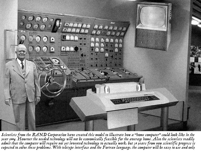
It is a gag. This photo is described in detail on snopes (a "mythbusters"
site). The base setup is actually a submarine control room in a museum to
which a few things have been changed and added and the description created.
>> This has got to be a gag, but what's its origin?
>>
>> http://subjunctive.net/images/2004/rand-home-computer.jpg
>
>I don't have graphics, but I think most of the picture you're
>talking about is a nuclear sub's reactor/electrical/steam control
>panel that's on display in the Smithsonian, with a DECwriter
>and guy and TV screen photoshopped on top. Am I too far off?
I do it the old fashioned way, with a high-speed connection, two browser
sessions, and stop watch!
>I think that hidden away in the Ebay user license is something about how
>external services have to pay some sort of fee in order to interface with
>Ebay. This is why there are not hoards of freeware versions of Power
>Lister, and anooyingly to me, not a good Mac version. This is also
>probably why free sniping programs are not forthcoming.
>
>I suppose Ebay can invalidate bids or users that use services that do not
>pay this fee.
>
>Time to move off Ebay, folks.
>
>William Donzelli
>aw288 at osfn.org
"Zane H. Healy" <healyzh at aracnet.com> wrote:
>>Saw an interesting discussion about CD-ROMs with MSCP SCSI (YES, a
>>CD-ROM ISO with XXDP would be truly awesome!) and this got me thinking
>>about my own UC07 controller - if I've understood correctly, this
>>controller does not support SCSI tape.
>>
>>I don't really know anything about MSCP or the SCSI command set that CD
>>writers use - but could a CD-R(W) drive be used as a backup device?
>>
>>I know it's bad style to do backups on CD-R, but bear with me :)
>
> I don't see why not, but you'll have to write the software to control it.
I very much doubt it. Writing to a CD-R is not done the same way as
writing to a disk. And MSCP-SCSI controllers only do writes as to a disk.
CDs need to have lead-ins, lead-outs and whatnots in between.
(Underruns, anyone?)
> You're also likely to find that it's very picky about what it will work
> with. At least with my Viking QDT and UDT controllers I *think* 512-byte
> blocks are a requirement, and I know they won't work with all 512-byte block
> CD-ROM drives.
My CMD controllers have been happy with every CD drive I've tossed at
them, but I admit it hasn't been that many different models, so I might
have been just lucky.
> An easier sollution is to have the SCSI HD's in removable trays, and Have a
> modern Unix box with the same type SCSI tray. Plug the PDP-11 disk into the
> Unix box, and use 'dd' to image the disk. The resulting image can even be
> used under SIMH.
That would definitely be easier. If you wanted backups, you could then
burn that image to a CD on the Unix box.
>>Also, now that I think about it, the perverse bugger that I am, could an
>>MSCP controller send an Audio CD Play/Next Track/etc. command to the
>>CD-ROM? Would be awesome to have a hifi controlled by the PDP-11. :)
>
> No clue, but I rather doubt it.
Same problem. SCSI command to play around with audi CDs don't have any
corresponding stuff in MSCP, so there is no way to map that.
In short, MSCP can't do it. Don't matter what SCSI can. You are limited
to what MSCP can do, since it is a MSCP controller. What it talks at the
other end is pretty irrelevant.
Johnny
--
Johnny Billquist || "I'm on a bus
|| on a psychedelic trip
email: bqt at update.uu.se || Reading murder books
pdp is alive! || tryin' to stay hip" - B. Idol
Hey, I have two MSV11-QBs here, each 2 meg parity QBUS memories.
I'd like to put both in the same system, creating a 4 meg PDP-11, but I
can't find the DIP switch settings for them.
The PCB in the PDF has the DIP switches placed differently on the board,
and the settings I try don't seem to work, I'm throwing memory errors,
and the boards appear in the wrong places.
the PCB revision is 5017547-01-D1-P2 while the PDF depicts a C1. I don't
know if that's the problem, but the boards do look different.
What I previously had was
__Q22_______ _______Q/CD______
/ \ / \
|Emul|DHV-|DHV-|DELQ|Gran|MSV-|PDP-|
|ex S|11 |11 |A |t co| 11 |11/ |
|CSI | | | |ntin| |83 |
| | | | |uity| QB | |
| | | | | | 0- |CPU |
|----| | |----|----| 2m | |
| | | | | | | |
| | | | | | | |
| | | | | | | |
| | | | | | | |
| | | | | | | |
7 6 5 4 3 2 1
What I've changed it to is:
_______Q22_______ _______Q/CD______
/ \ / \
| |TK50|DHV-|DHV-|DELQ|MSV-|MSV-|PDP-|
| |Cont|11 |11 |A |11 | 11 |11/ |
| | | | | | | |83 |
| | | | | | QB | QB | |
| | | | | | 2- | 0- |CPU |
|----|----| | |----| 4m | 2m | |
|RQDX|Emul| | | | | | |
| 3 |ex S| | | | | | |
| |CSI | | | | | | |
| | | | | | | | |
| | | | | | | | |
8 7 6 5 4 3 2 1
With both memory boards in, the CPU diag ROM reports that I have small
ROMs placed around the memory space and one RAM board somewhere in space
of some strange size. I assume that's because the DIP switch settings
are wrong.
Anyone have the docs? Or know what the DIP switch settings are for
setting them to 0-2M and 2-4M?
Thanks very much in advance for your help!
-toresbe
I was contacted by a gentleman who wishes to purchase an ADM-3A.
He is located in Northern VA.
If anyone can help, please contact Jim at:
jAt {at} feeCzell {dot} Ccom
[Remove the capitals and do the appropriate conversions]
Or contact me and I will pass it on.
Dave
--
dave06a (at) Dave Dunfield
dunfield (dot) Firmware development services & tools: www.dunfield.com
com Collector of vintage computing equipment:
http://www.parse.com/~ddunfield/museum/index.html
>From: "Miriam Mustain" <pmustain at ispwest.com>
>
>We are in San Diego, California. Mir
>
>>Hi:
>>My mother has the following equipment and would be willing to donate it if
>you could pay the shipping.
>>
>>Macintosh Plus 2MB
>>Model # M0001A
>>Serial # *F745B8SM0001A*
>>FCC ID # BCG9GRM0001A
>>MacWrite and MacPaint discs
>>
>>Apple 3.5 Drive
>>P/N 825-1304-A
>>Serial # Y780BFJ
>>
>>Image Writer II Printer
>>Model # A9M0310
>>Serial # 0591245
>>FCC ID # BCG9BUA9M0310
>>
>>The printer is a very pale yellow color in comparison to the neutral tan of
>the computer. I can't tell whether this is due to age or its original
>color.
Well, I've been messing with the 11/34 on and off now for a few months as I
feel like it.
The problem right now is that I have no light on the H745 power regulator.
Both lights are on, on the two H7441s in the other slots.
If I need to measure draw on the backplane to solve the problem, where do I
do it from? If on the power distribution board or backplane, then at what
points?
Secondly, do certain modules need to be installed to utilize the H745's
resources? (i.e. a device that uses -15vdc) or should the light come on
anyway from just being connected to the power distribution board? I've
tried with both those modules in and removed from the system, and it didn't
seem to make a difference.
What do I need to do to diagnose this problem? It's really driving me nuts.
Appreciating any help you can give,
Julian
I was showing someone my collection, and while standing in front of my 11/45
restoration project I lamented about how those little black plastic brackets
that attach to the upright rails just can't be found anymore. You know the
ones... the bracket has two round knobs that always break off - these are
used to mount DEC filler panels.
He said he knew a plastics firm that may be able to do a short run at a
reasonable price. Failing that, he felt another company he knows of may be
able to make them out of metal. This gives rise to two questions...
1) Would replicas made of metal work as well as replicas made of plastic?
2) How many people would be interested in some if the price is reasonable?
And how many? I know a few of my systems I'd go back and use 4 brackets on
each panel instead of the 2 I skimped on. In addition, a few racks I simply
couldn't mount filler panels at all because of no brackets. Of course,
before the guy can quote me a price I need to give him a firm minimum count.
The more in the firm count the lower the price is. I figured I'd order 40 or
50 if the price was reasonable. But I'm sure my own order would be cost
prohibative unless other collectors jump in.
On the other hand, if some collector has a big crate of these, I'd rather
just buy pile of originals :)
Jay West
I found these tapes in an old warehouse today. They are with original IBM
lables, but I'm offering them as scratch media. There are six tapes, labled
as follows:
9404-E10 Model P/N 0421F3011 (OS?)
AS/400 Control Language 1988 V1.3
IBM AS/400 System Program V3 tape 1 of 4
.... tape 2 of 4
.... tape 3 of 4
.... tape 4 of 4 (includes complete PTF's)
Tapes are QIC-6525, and are available free for shipping costs.
Jay
All:
As I clean the shop a bit I've come across a few things to
trade. As I continue working, I'll pull some other things together and post
them.
So far:
* NEC 8080 evaluation kit "EVAKIT-8" includes board and manuals.
* "Inside Commodore DOS" book
* Various BYTE mags (YR:MO):
o 75/12
o 76/4
o 77/2, 3, 10, 11
o 78/1-6, 9
o 79/1, 5-7, 9, 10, 12
o 80/4, 7, 1, 10
o 81/3-5
o 82/full year
o 83/3, 8
o 84/3
Wanted:
* "vintage" 5.25" external floppy drive case suitable for two drives
(preferably full-height but half-height OK)
* CP/M boot disks/CBIOS/loader listing suitable for SD Sales
VersaFloppy controller
Location: 11791
If interested, please contact me off-list. Thanks.
Rich
Rich Cini
Collector of classic computers
Build Master for the Altair32 Emulation Project
Web site: <http://highgate.comm.sfu.ca/~rcini/classiccmp/>
http://highgate.comm.sfu.ca/~rcini/classiccmp/
/************************************************************/
I actually think I saw a system like this at the local computer surplus
place about a year ago. It had a display like a Microfiche viewer with
a MO disk drive and a hard copy output connection to a laser printer.
Somewhere I have one of the disks.
*****PREPARE FOR LONGWINDED COMMENTS*****
I'll bet the data is not in a standard format. The hospital where I work
has lots of MO disk using systems, CT scanners, data backups for patient
monitoring, Cardiology cath lab and they all use non standard data
formats. The CT and cath lab are the worst they use a raw file
structure that is directly read and written by the system. They also
encode the data in a compressed format to pack more data on the disk.
The MO disk media manufacturers are also not producing the media any
more.
I have several of the drives but we have never been able to read one of
the disks without the drive it was originally created on. The venders
consider the storage format proprietary and will not release it.
Back 10-12 years in the past we reverse engineered the data structure
that was on an LMSI 12" optical drive containing digital x-ray images.
There was a hierarchy on the disk and the data was stored in a run
length encoded format of the differences between different resolutions
of the images. We made disks up with 1 image and then compared it to a
blank disk, then added an additional image and repeated the process. We
were eventually able to read the disks offline and purchased LMSI drive
to connect to our VAX.
We have this exact problem today, a SCSI MO disk from a GE CT scanner
and no system to read it. We kept the drive but there is no software.
GE will sell you a system with software to read the disk for $20,000 or
transfer an individual disk for a fee.
Mike
I don't know if it was due to cctalk'ers or not, but ebay just gave me
$100 gift certificate for the serial terminals guides that I wrote.
If you voted my guide(s) as useful, thanks!
--
"The Direct3D Graphics Pipeline"-- code samples, sample chapter, FAQ:
<http://www.xmission.com/~legalize/book/>
Pilgrimage: Utah's annual demoparty
<http://pilgrimage.scene.org>
Can you run RSTS on a VAXserver 4000? It just occurred to me that
this might be possible. From my personal usage I had only thought of
RSTS in a PDP-11 context. If it can run, am I limited to using a
particular version (presumably because it would need VAX support?).
PS: Recent addition to LibraryThing: VAX Systems & Options Catalog
1988. I will be scanning/uploading the pages on the VAXstation 8000
to my web area soon as this is a machine with E&S 3D graphics
hardware.
--
"The Direct3D Graphics Pipeline"-- code samples, sample chapter, FAQ:
<http://www.xmission.com/~legalize/book/>
Pilgrimage: Utah's annual demoparty
<http://pilgrimage.scene.org>
Saw an interesting discussion about CD-ROMs with MSCP SCSI (YES, a
CD-ROM ISO with XXDP would be truly awesome!) and this got me thinking
about my own UC07 controller - if I've understood correctly, this
controller does not support SCSI tape.
I don't really know anything about MSCP or the SCSI command set that CD
writers use - but could a CD-R(W) drive be used as a backup device?
I know it's bad style to do backups on CD-R, but bear with me :)
Also, now that I think about it, the perverse bugger that I am, could an
MSCP controller send an Audio CD Play/Next Track/etc. command to the
CD-ROM? Would be awesome to have a hifi controlled by the PDP-11. :)
TIA,
-toresbe
check out www.bidrobot.com
they charge a flat subscription fee. You can spend as little or as
much and it won't cost you anything but what ever you buy.
best regards, Steve Thatcher
At 04:57 PM 3/2/2006, you wrote:
>eSnipe charges 1%. Most of my purchases are less that $100 so a few
>cents for a service that allows me to do something else instead of
>watching an auctio is worth it to me. To each their own.
At 03:08 AM 3/3/2006, Willi Kusche wrote:
> I did all my development on a Commodore 32K PET equipped with an S-100 buss
>adaptor. The S-100 buss had a 32K RAM card and a Versafloppy disk controller
>card connected to two 8 inch single sided single density drives. All the
>source is on 8 inch disks. I still have the disks but the question now is, did
>the disks keep? The system is still set up in the den but it's been years since
>I've turned it on. Now, I'm afraid of what will happen if I try to power it up.
Yes, the old capacitors in the power supply may have trouble.
But the disks are probably OK. They used big, long-lasting bits
back then. I am sure some of the folks on the Classic Computer
Collector mailing list http://classiccmp.org/ can give advice about
how to read those floppies. If the PET was just handing it
sectors, it's just a matter of reading the raw sectors and
then reassembling it into a disk image that could be handled
by some other utility.
- John
A friend of mine has three HP 7906 drives that he wants to get rid of.
Two of the drives look complete and in very good condition, the third looks
complete but is missing the front face plate. He's asking $50 each. They're
in Sanford Florida and will need to be picked up in person. SHIPPING,
STORAGE, DELAYS, ETC ETC ETC IS NOT AN OPTION! DON'T EVEN ASK. We've tried
that before it didn't work! We'd like them gone ASAP!! If seriously
interested call Art directly at (407) 402-6361. We do have a forklift,
pallets, etc available so you can pack and load them but we're not going to
spend our time doing it. We have too many other projects that we're already
way behind on.
Joe
I exchanged several emails today with an eBay seller offering an Altair
system with disk drive for a starting bid of $2 in a one-day auction.
This is a bogus offer - I became uneasy when the seller solicited an
offline offer in response to a query about shipping but insisted on
payment through Western Union rather than PayPal, even though the
orginal auction listed PayPal as a preferred option.
It is interesting to note that the auction I saw this morning (offered
by seller DOCHANDS) was cancelled by eBay almost immediately but the
_identical_ auction (same pictures and extensive text) is currently
(2/21/06 @ 11:31 pm) being offered by two different sellers - as auction
6038449898 by GUNDAN760 and as auction 6038549050 by SHARISINA. It looks
like the "seller" is hijacking legitimate eBay accounts to use as bogus
fronts for his dealings.
Caveat emptor.
Jack
--
No virus found in this outgoing message.
Checked by AVG Free Edition.
Version: 7.1.375 / Virus Database: 267.15.12/265 - Release Date:
2/20/2006
what you get someone whos got everything else. Or at
least every other IBM incompatible on the planet (ok
Im not quite there). Also a must for the truly
masochistic (gcr floppies). What every guru/sicko
needs. Alas the shipping is prohibitive if youre on
this side of the pond.
--- Free_Software_for_DOS at yahoogroups.com
<d_andrianov at mail15.com> wrote:
>
> I don't know if there is a mirror... But I have
tried
> downloading the files again and it works! Try
> downloading later. By the way, the program is just a
> much more functional version of GS which is already
on
> the Free Software For DOS website.
>
> Denis
>
>
> > Short Stop's Pages
<short_stop_for_software at yahoo.com>:
>
> > On 9 Feb 2006 Denis Andrianov wrote (snipped):
> >
> > > Tja, hier habe ich geplant, andere Programme zu
> stellen, die
> > > eventuell von Nutzen sind. Die kriegen
allerdings
> keine technische
> > > Unterstützung* von mir. Aber ich freue mich
> auf Bescheid, wie
> > > das Programm bei dir funktioniert hat... and
bugs, too!
> >
> > :) I recognized that broken German text,
because...
> >
> > > Hi everyone. It has been very quiet lately on
this
> > > mailing list. Anyway, here is something
interesting. A
> > > new (2005) port of Ghostscript is now available
for
> > > DOS. ............ Please
> > > add this link to the Free Software for DOS site:
> > > http://www.caddit.net/programming.php.
> >
> > ... I've visited that site repeatedly since
December,
> and tried to
> > download the Ghostscript binary and source
packages,
> but no luck - the
> > server stops serving. I know for sure that's the
> problem, because I get
> >
> > its timeout message, appended to the part of the
ZIP
> file that actually
> >
> > comes down the pipe.
> >
> > So until that problem gets fixed, and I can look
the
> program over, I
> > can't recommend it in the Free Software pages.
> >
> > Denis - do you know if there is another download
site?
> >
> > Peace,
> > Steve @ Short.Stop
> >
> >
> >
> > __________________________________________________
> > Do You Yahoo!?
> > Tired of spam? Yahoo! Mail has the best spam
> protection around
> > http://mail.yahoo.com
> >
> >
> >
> > Yahoo! Groups Links
> >
> >
> >
> >
> >
> >
> >
>
>
>
> Yahoo! Groups Links
>
> <*> To visit your group on the web, go to:
>
http://groups.yahoo.com/group/Free_Software_for_DOS/
>
> <*> To unsubscribe from this group, send an email
to:
>
Free_Software_for_DOS-unsubscribe at yahoogroups.com
>
> <*> Your use of Yahoo! Groups is subject to:
> http://docs.yahoo.com/info/terms/
>
>
>
__________________________________________________
Do You Yahoo!?
Tired of spam? Yahoo! Mail has the best spam protection around
http://mail.yahoo.com
Hi,
Sorry to trouble you but I have found a 50 pin SCSI Insite I 325VM floptical
drive amongst my Amiga bits. Can this read/write to Amiga 880K floppy disks
please? What else can it do?
Regards,
Danny.
Hi Teo,
Did you get any info on the Q-920. I also have one, without manual, and
would like to get a manual too.
Thanks
Have a fantastic day.
Kind regards,
Memex Electronics Inc.
Wally Cassell
777 Walkers Line
Burlington ON
Canada L7N 2G1
ph (905) 635-3040
fax (905) 631-9640
www.memex.ca
sales at memex.ca
---
Outgoing mail is certified Virus Free.
Checked by AVG anti-virus system (http://www.grisoft.com).
Version: 6.0.443 / Virus Database: 248 - Release Date: 1/10/2003
Does anyone have information on the TI Travelmate LT220/V. A
quick Google didn't turn up anything of value.
I have acquired one with a pile of other items and have no idea
how useful it might be. The power source, 18V DC did not come
with it and there is no indication as to whether the center pin
of the power connector is the positive connection or not.
TIA
John
Another non-obvious possibility is that the disk jacket itself has been pinched around the edges and the extra friction is keeping the disk from spinning in the jacket. If you need the info off the disk, cut a small margin of the jacket off around the edges or you can remove the internal disk itself and put it in a known good jacket (cut just one end of the jacket for the disk to slide back into the jacket). Experiment...
best regards, Steve Thatcher
-----Original Message-----
>From: Tony Duell <ard at p850ug1.demon.co.uk>
>Sent: Mar 2, 2006 1:31 PM
>To: cctalk at classiccmp.org
>Subject: Re: Fixing 8" disk hubs
>
>>
>> All:
>>
>>
>>
>> I'm restoring an IMSAI system which has an Icom "Frugal Floppy"
>> system setup (8" FD-400 drives). I've been getting CRC errors since I got it
>> running a few weeks ago, so I decided to run it with the cover off to try to
>> see what's going on. Tonight I noticed that the floppy disk itself wasn't
>> spinning. The hub engages when the door closes but it must be *just* missing
>> contacting the diskette by *this* much.
>>
>>
>>
>> What kind of tricks are people using to improve the contact
>> between the floppy disk and the spindle hub? I remember they made "hub
>> protectors" for 5.25" disks - is there something similar? Other ideas?
>
>I think you're going about it in the wrong way. If the disks are not
>obviously physically damaged (and you don't mention that they are), the
>drive should grip them. If it doesn't, the fault is with the drive, not
>with the disks. And I never believe in 'curing the symptoms'
>
>For some reason your drive is not clamping the disk properly. Maybe
>there's a spring that's not providing enough tension. Maybe a mechanical
>latch is not alighned properly and the clamp is not held down far enough.
>I would start looking at something like that.
>
>-tony
Hi,
I'm trying to track down a copy of a datasheet from the Hewlett Packard
1989 Optoelectronics Handbook. Does anyone have a copy of this databook
lying around somewhere?
The datasheet I'm after is the one for the Thinkjet printer head - part
number believed to be 51604A, though this may be different to the one in the
databook (HP have this rotten habit of 'improving' things and changing the
part numbers in the process).
Thanks.
--
Phil. | Kitsune: Acorn RiscPC SA202 64M+6G ViewFinder
philpem at dsl.pipex.com | Cheetah: Athlon64 3200+ A8VDeluxeV2 512M+100G
http://www.philpem.me.uk/ | Tiger: Toshiba SatPro4600 Celeron700 256M+40G
To: classiccmp at classiccmp.org
We offer a unique "instant online conversion" service, which converts your files between most word processor, spreadsheet and graphics file formats, internet formats such as HTML and XML (including to Microsoft Office 2003 XML), and also some data base formats. It also performs letter-perfect conversion of almost any such file to PDF. IT CAN CONVERT BETWEEN MORE FILE FORMATS, AND CONVERT MORE ACCURATELY THAN ANY OTHER ONLINE CONVERSION SERVICE WE KNOW OF!
This service is available 24/7. There is no software to purchase, nor any subscription fee or commitment. You just pay as and when you need to convert files. Converting a small set of files costs as little as $9.
This is an easy-to-use and reliable conversion service. From the service's web page, you click a "Convert" button, drag files to be converted into a dialog box that appears, and enter payment information. Your files are then uploaded to our conversion server, and in a couple of minutes the converted files are downloaded back to you. It's as simple as that. The whole process is automatic and very easy to use. All communication is encrypted and there is no security compromise. Please see http://www.acii.com/online.htm for more details.
This service is particularly useful for conversions you run into occasionally, or for which off-the-shelf conversion software is not available. We welcome you to give this service a try. Please see http://www.acii.com/online.htm for a detailed listing of the file formats, pricing and other details.
If you have any questions please let us know (simply respond to this email). To be removed from this mailing list, please respond with the single word "remove" in the subject line.
Best Regards,
V. Saini, for
Advanced Computer Innovations, Inc.
ADDRESS: 656 Kreag Road ~ Pittsford, NY 14534-3730 (USA)
PHONE: (US)-585-385-3810 | FAX: (US)-585-385-6822
WEB: http://www.acii.com
I'm sending this one message to everyone who replied. Thanks guys...
Anyway, here is everything I know about these discs. Unfortunately, the
guy who knew about these is long gone (the usual ;).
They are Canon CanoFile 502M Magneto Optical discs. Double sided, 256 MB
per side. Physically they are 5 1/4" x 6". They were used in a Canon
document imaging system. Don't know what OS it ran on.
As it stands right now, it appears that the discs with the data we need
aren't here. But we still want info about what we may need, and how much
it'll cost, if we do need to read these in the future.
Thanks again...
--
--- Dave Woyciesjes
--- ICQ# 905818
--- AIM - woyciesjes
All:
I'm restoring an IMSAI system which has an Icom "Frugal Floppy"
system setup (8" FD-400 drives). I've been getting CRC errors since I got it
running a few weeks ago, so I decided to run it with the cover off to try to
see what's going on. Tonight I noticed that the floppy disk itself wasn't
spinning. The hub engages when the door closes but it must be *just* missing
contacting the diskette by *this* much.
What kind of tricks are people using to improve the contact
between the floppy disk and the spindle hub? I remember they made "hub
protectors" for 5.25" disks - is there something similar? Other ideas?
As always, thanks.
Rich
Rich Cini
Collector of classic computers
Build Master for the Altair32 Emulation Project
Web site: <http://highgate.comm.sfu.ca/~rcini/classiccmp/>
http://highgate.comm.sfu.ca/~rcini/classiccmp/
/************************************************************/
Hi
Also, make sure that the disk isn't being clamped
too tightly by the disk envelope. I've seen this
happen a number of times by disk that were stored
tightly in a bunch of disk.
Things usually work OK if I manually rotate the disk
in the envelope a few times but I've had to remove
the disk from the envelope in a couple cases.
Dwight
>From: ard at p850ug1.demon.co.uk
>
>>
>> All:
>>
>>
>>
>> I'm restoring an IMSAI system which has an Icom "Frugal Floppy"
>> system setup (8" FD-400 drives). I've been getting CRC errors since I got it
>> running a few weeks ago, so I decided to run it with the cover off to try to
>> see what's going on. Tonight I noticed that the floppy disk itself wasn't
>> spinning. The hub engages when the door closes but it must be *just* missing
>> contacting the diskette by *this* much.
>>
>>
>>
>> What kind of tricks are people using to improve the contact
>> between the floppy disk and the spindle hub? I remember they made "hub
>> protectors" for 5.25" disks - is there something similar? Other ideas?
>
>I think you're going about it in the wrong way. If the disks are not
>obviously physically damaged (and you don't mention that they are), the
>drive should grip them. If it doesn't, the fault is with the drive, not
>with the disks. And I never believe in 'curing the symptoms'
>
>For some reason your drive is not clamping the disk properly. Maybe
>there's a spring that's not providing enough tension. Maybe a mechanical
>latch is not alighned properly and the clamp is not held down far enough.
>I would start looking at something like that.
>
>-tony
Being a member of the PDP-1 Restoration Team at the Computer History Museum, I
can assure everyone that this vendor doesn't have a clue (or is a fraud).
I thought at first that he made a typo in the title - but no, he also restated
"PDP-1" in his "RARE" article description statement. Sigh.
Title: RARE DEC PDP 1 MEG MEMORY BOARD BY EMC CORP. Item number: 8773655976
Desc: THIS IS A RARE DIGITAL EQUIPMENT PDP ONE MEG MEMORY BOARD MADE BY EMC
CORP.IT IS GAURANTEED TO BE WORKING.
I'm tempted to buy it and then tell him I tried it out, and I couldn't make it
"fit". ;-)
Nah, that's too much work...
Lyle
--
Lyle Bickley
Bickley Consulting West Inc.
Mountain View, CA
http://bickleywest.com
"Black holes are where God is dividing by zero"
Not exactly sure what they are worth, but I have a few older
computers that are looking for a home.
AT&T Unix PC (has internal HD, software loaded but don't have the
passwords!)
Vector Graphic Memorite system (with manual) - Not terribly common
>from what I've been told
Original IBM PC & Printer (both in zip up bags)
I'd be glad to chat with anyone interested in these machines (trading
may be considered as well). I am located in Columbus, Ohio and could
ship (but these things aren't exactly light!) I will be moving soon
and I just don't have the room to take everything with me, so
hopefully someone is interested!
-Chris
Hello I am a student at SJSU in CA and I am wanting to construct a
talking DVM senior project. Part of the speech circuit would be using
the the DT1050 kit by National semiconductor(MM54104 +ROMS for the
digitalker). Do you know of any anywhere? If so,let me know....
Thanks
Paul
-------------------------------------------------------------------------------
This message and any included attachments are from Siemens Medical Solutions
USA, Inc. and are intended only for the addressee(s).
The information contained herein may include trade secrets or privileged or
otherwise confidential information. Unauthorized review, forwarding, printing,
copying, distributing, or using such information is strictly prohibited and may
be unlawful. If you received this message in error, or have reason to believe
you are not authorized to receive it, please promptly delete this message and
notify the sender by e-mail with a copy to Central.SecurityOffice at shs.siemens.com
Thank you
Phillipe,
I am working on a project that will allow me to test many/most of
my flip chips as you did. I got the idea from seeing what you did
on your web site. I am hoping mine is not quite as bad off as
the one you fixed. It was fully functional, and still partially
is. My main problem right now is I have no memory access. I hope
as have as much luck as you did. I like my 8i system, as it's what
I originally learned on and finally got one of my own.
Tim R
--- On Wed 03/01, Philippe Sonnet < sonnet at sols.ucl.ac.be > wrote:
From: Philippe Sonnet [mailto: sonnet at sols.ucl.ac.be]
To: cctech at classiccmp.org
Date: Wed, 1 Mar 2006 23:10:57 +0100
Subject: Re: My pdp-8i problem
Dear Tim,It is very hard to answer your question. I also spent hours fixing my pdp-8/L, in which almost all circuits had to be repaired. It took me two years. The only way : use a logic probe and have a set a spare flipchips which you know are OK. I created a system to test the flipchips using a digital acquisition card on a PC (see www.sonnet.be). Collect all possible schematics, study them, have a confortable seat, stay calm and systematic and use a card extender to have better access to all the lines. Good luck,Philippe
_______________________________________________
Join Excite! - http://www.excite.com
The most personalized portal on the Web!
>From: "John C. Ellingboe" <john at guntersville.net>
>
>Chuck Guzis wrote:
>>
>> On 3/1/2006 at 3:07 PM John C. Ellingboe wrote:
>>
>> >Does anyone have information on the TI Travelmate LT220/V. A
>> >quick Google didn't turn up anything of value.
>> >
>> >I have acquired one with a pile of other items and have no idea
>> >how useful it might be. The power source, 18V DC did not come
>> >with it and there is no indication as to whether the center pin
>> >of the power connector is the positive connection or not.
>>
>> Any external I/O connectors on it? Things like parallel port connections
>> will usually have their ground/return pins conected to the - side of the
>> power supply.
>>
>> Last resort is popping the box open and checking the ground plane on the
>> PCB or any of the ICs (if the ground plane is buried) against the
>> connector.
>>
>> Cheers,
>> Chuck
>
>I haven't opened it up yet but there is a 9 pin jack on the
>side, maybe a serial port. It also has a modular connector
>which may be a modem connection. The other side has a large
>connector behind a hinged cover that looks like it may be a bus
>connection for expantion or connection to some special
>equipment.
>
>John
Hi John
The point is that it is unlikely that the 18 volts will
go to one of these connectors but the ground lead will
most likely be there and Ohm at zero Ohms between connectors.
The other 18 volt lead will most likely be the positive.
Dwight
the talk of a peculiar USR pc made me remember this.
There used to be a (primarily) electronic junk store
in LI called Eldies (Edlies?) on Hempstead Tnpk in
Levittown I guess. Sitting there one day was an all in
one, IIRC, NCR unit that booted up to an a:> prompt.
It struck me as a weirdish dos semi compatible. It
didnt strike me as a PC4 or the nearly identical
Decision Mate (cpm). Pretty sure it was NCR, but eh
maybe it was NEC (definately NOT an APC, not quite
that big and heavy). Anyone have a clue?
__________________________________________________
Do You Yahoo!?
Tired of spam? Yahoo! Mail has the best spam protection around
http://mail.yahoo.com
Hi Mr. Hoke,
I saw your posting on the web about installing an old 5 1/4'' Floppy on a
new PC.
I got the same floppy ( TEAC FD-55GFR ) and would like to know whether you
succeeded in the end, and how you jumpered your drive. I get an E/A-Error
message from WindowsXP whenever I try to click on the drive in the Explorer ...
but XP at least recognizes it as 5 1/4''-floppy.
Regards.
Alexey.
Hi - I am trying to install a Teac FD-55GFR 5 1/4" drive into a Pentium 200
mhz computer. Upon trying to read the drive I get a "General Failure Trying To
Read Drive A" error message. I have the drive connected to the end of the
ribbon cable, and the drive is designated as drive A. Also, I noticed that
there are some switches (I forgot what they are called - upright posts where you
couple a pair together using a U-shaped something or another) on the bottom of
the drive. How should these switches be set? Also, could my problem be that I
am not using a correct BIOS?
Thanks for all of your help.
I was hoping someone on this list might have some input on this. I have also posted this to alt.sys.pdp8. I have a pdp-8i with a memory problem. Here is the post from alt.sys.pdp8:
Quite some time back while scoping out a problem I shorted a pin in my
8i backplane and lost memory control. Since that time Vince and I have been trying to figure out where the problem is to fix it. I don't know what pin I shorted as at the time I did not realize
I had damaged anything. The +5v breaker tripped though.
The problem is I can not deposit or read back any memory locations.
The MB is displayed correctly on a deposit. Scoping signal has shown me a very odd signal on B FIELD 0 (1) when the machine is in run mode. It has a wave form on it rather than just a normal
voltage. The oddest thing is the high point of the wave goes up to +6v with a bit of the beginning of the top portion going above +6v. To me this should not be. How can I get
+6v from a system that is using +5v as it's input voltage? We have
some theories but nothing concrete as yet. The other thing is if I remove all 3 G228s (A36, B36, B37) the
signal goes away. I do not have parity memory so nothing is in A37.
We believe there is a bad ground somewhere, but I have not been able to determine where. I do not have a wiring list so I may have to trace some signals manually. I think I have to find all the places the B30L1 (B FIELD 0(1)) goes to.
Any ideas or suggestions from anyone? This has been bugging me for a
long time. I look at it for awhile, and then put it down for awhile. It's also not easy to look at this in the location it is in. It's too low to kneel and really be comfortable. Too high to lay on my stomach. :)
Thanks for any input on this. I should say that part of the system
still works. Examining or depositing memory while it does not appear to load/store the data increments the PC
as it should. I can sort of run, which was my original problem. It
runs but stays at location zero. It is not an interrupt causing this. So the front panel is mostly operational
so at least some of the machine is still working. I just have to find
the problem with the memory.
I know most people on this list do not have a pdp-8i, nor may know
much if anything about them. Any suggestion will be taken and looked
into if it seems to have hope of leading to a solution. Also I will
answer any questions people have to help describe the problem more or
give more details into what Vince and I have looked at.
Tim Radde
_______________________________________________
Join Excite! - http://www.excite.com
The most personalized portal on the Web!
Can anyone help this guy?
>From: Gary E Kaufman <gkaufman at the-planet.org>
>Subject: Computime S-100 card docs?
>
>A long shot - I found your old message on classiccmp.org. Any chance you
>located docs for the Computime UFDC-1? I have two of the boards but have
>lost the docs.
>
>Many thanks!
>
>- Gary
>
>
Discovered on the new "Google Video" tapings of the Computer History
Museum Meetings, like "An evening with Steve Wozniak" Jan 12, 2006.
For more search Google Videos for Computer History Museum.
Some good National Historical Archive stuff too.... like the moon landing.
Found under google picks. Plays fine on my Ubuntu Linux box, too.
--
Paxton Hoag
Astoria, OR
USA
Greetings,
I have a pair of DECstations and related parts that I don't forsee
doing anything with in the near (or distant) future:
* Complete DECstation 5000/133 with display, mouse and keyboard that powers
up but has no OS.
* DECstation 2100 system unit only. Unknown condition.
* Storage expansion unit with one hard drive
* Three other DIGITAL mice NIB (maybe for the 2100)
* Another DA-15 to keyboard/mouse cable for the 5000
* Ethernet tranceiver
Photos can be found at:
http://popcorn.cx/computers/digital/decstation2100/http://popcorn.cx/computers/digital/decstation5000/
Pickup is from Glen Waverley, preferably early evening later in the week.
I hope someone else can get better use out of them than I have.
Thanks,
Stephen
Update to the previous update which was an update as well: David said that
after his speech, he'll auction an original copy of the first edition of
"Basic Computer Games" and also the first 12 issues of "Creative Computing"
magazine, with the money going to charity.
-----------------------------------------
Evan Koblentz's personal homepage: http://www.snarc.net
Computer Collector Newsletter:
>> http://news.computercollector.com
Mid-Atlantic Retro Computing Hobbyists & Museum:
>> http://www.marchclub.org
>> http://groups.yahoo.com/group/midatlanticretro/
Does anyone know if a 2111 256x4 SRAM is a 0.3" or 0.4" wide
package? I've found a datasheet, but it doesn't list the actual width.
It refers to a package type that I can't find any data one.
Thanks,
--jc
Can anyone tell me useful stuff about the Panasonic RL H1400 computer? I
believe it was also sold under the Quasar brand name.
I've just bought one. As well as the machine (which I've not tested yet),
I got a little thermal printer/cassette interface, the AC adapter (for
110V mains), and 13 EPROMs in carriers. These seem to be insurance
programs (what a suprise -- NOT), but are at least UV-erasable EPROMs.
A few things :
I have of course taken it apart, it is painful to dismantle with wires
soldered between everything. The contemporary HP machines are a lot nicer
to work on.
With the bottom cover removed, you see the component side of the CPU
board. I recognise the 6502 processor, some TTL and 4000-series CMOS
chips, 2 8K ROMS soldered in, and 2 6116 (2K each) SRAMs. There's also a
square PQFP chip, looks to be custom (I/O???). Alongside that board is a
6V NiCd pack with a fuse in series.
A bit more desoldering and unscrewing let me flip that board out of the
way. On the underside is another TTL chip and a lot of SMD passives, etc.
The other PCB carries the keyboard contacts, the display, half-a-dozen
Epson PQFP chips (display drivers?) and a couple of 4071s, which IIRC are
OR gates.
There's an expansion connector on the end of the CPU board. 44 contacts.
Looks to be the 6502 bus + power some others.
The printer also comes apart from the bottom. Its PCB contains a 4K ROM,
an 80 pin PQFP ASIC, a driver chip, and a few small logic chips. Getting
ito the rest of the machine is a bit more tricky, all it contains is the
printer mechanism and 4.8V-worth of NiCds.
I also cracked open the mains adapter.More complicated than I thought,
there's a regulator chip in there. And a fuse mounted in clips (what is
the point of a clipped in fuse inside a glued case??).
Anyway, I've done a web search. Nothing very useful turned up. I did read
a user manual on one site, which told me little that wasn't obvious.
Anyone got any technical information on it? Any useful software?
-tony
A while back I asked if anyone had an interest in my vintage (early
90s) data books. With librarything, I've decided to add them to my
library by scanning the covers and creating entries for the databooks.
Each of these entries is tagged "data book", with title, year and
manufacturer for each one. I'll be adding the remainder of the
12 linear feet of shelf space over time. So if you see something
there that you'd like more information about (chips covered, maybe
scans of the table of contents), let me know.
<http://www.librarything.com/catalog/legalize>
--
"The Direct3D Graphics Pipeline"-- code samples, sample chapter, FAQ:
<http://www.xmission.com/~legalize/book/>
Pilgrimage: Utah's annual demoparty
<http://pilgrimage.scene.org>
Hello All,
I have a nice Compaq Portable II that I just put a 1.44 3.5" drive into and now I see that the tech manual says that I need the upgrade rom N3 to see the drive. Any chance that anyone has this rom image or knows where to find it? Thanks a lot.
Ralph
I glommed onto a good deal of new canary 1 inch paper tape in rolls (about
nine inch diameter), for Teletype ASR 33s. After taking what I want, I
would like to trade the rest for unused punchcards or other mainframe
debris. Enquire within.
William Donzelli
aw288 at osfn.org
I was out of reach of emai when this was posted, but if anyone's still
interested...
On Feb 17 2006, 8:34, Lyle Bickley wrote:
> On Thursday 16 February 2006 20:49, compoobah at valleyimplants.com
wrote:
> > I have the IndiZone 3 CD- Don't know what the legal status is but
as they
> > gave them away for shipping . . . Another thing that would be nice
to have
> > would be IDO 4.1 for some of the older 4D IRI.
> As soon as I get out from under a bunch of "real business" work, I'll
check
> with SGI on this matter. I have still have a few good connections
internally
> at SGI, so it's at least worth a shot.
I have all (?) three Indyzone CDs (Tales From The Indizone, 5.2
edition, 812-8102-002, August 1993; Awesome Power In The Indyzone^2,
Summer Edition 1994, 812-8111-002; and Final Impact In The Indizone^3,
December 1995, 814-8111-003), and IDO 4.1.1 5/93, 812-0017-006. I also
have lots of HotMix CDs. My website hasn't enough capacity for even
one complete image, alas. But if anyone in the UK has a suggestion, I
might loan them.
--
Pete Peter Turnbull
Network Manager
University of York
Greetings,
I have a pair of DECstations and related parts that I don't forsee
doing anything with in the near (or distant) future:
* Complete DECstation 5000/133 with display, mouse and keyboard that powers
up but has no OS.
* DECstation 2100 system unit only. Unknown condition.
* Storage expansion unit with one hard drive
* Three other DIGITAL mice NIB (maybe for the 2100)
* Another DA-15 to keyboard/mouse cable for the 5000
* Ethernet tranceiver
Photos can be found at:
http://popcorn.cx/computers/digital/decstation2100/http://popcorn.cx/computers/digital/decstation5000/
Pickup is from Glen Waverley, preferably early evening later in the week.
I hope someone else can get better use out of them than I have.
Thanks,
Stephen
A while ago there was some talk about Ebay and not wanting to use Paypal
there for assorted reasons. Since I'm a relative newcomer to this list, I
figured I should wait before saying anything along these lines. So...
I'm in the business of selling classic computer stuff on Ebay under the ID
of "frotz661". See if you can guess the hidden references in that name.
Anyhow, I let some people talk me into accepting money orders. Then I got
burned by people who like to wait forever, money orders from Bumpassville
Supermarket, and so on. So I decided not to accept them anymore. You
guys seem to be a more reliable bunch, so if you email me ahead of time,
I'll accept a US Postal money order.
--
David Griffith
dgriffi at cs.csubak.edu
would it be accurate to say that a unit, such as my
Mindset II, which has the power switch built into the
keyboard turns the system on by asserting the
power-good signal (when the switch is activated)? I
know from the Byte article that an 8042 supervises the
keyboard (same or similar to the IBM PC/AT). I was
thinking I could tie something? to +5 volts in an
attempt to determine if my pos even works. And how far
is it from reality to suggest all pc kbs are the same
except for their 8048/9/8748/9 programming?
__________________________________________________
Do You Yahoo!?
Tired of spam? Yahoo! Mail has the best spam protection around
http://mail.yahoo.com
I've added a page to my website where I am posting
things I have to sell or trade. Currently have a
microVax 3100, DEC Storage Expansion, HP 9836, Sun
3/80 and Sun SparcStation 5. I'll be adding items as
I sort through things. Just don't have the time to
give these the attention they deserve so hope I can
find others who can. Most are in an unknown
condition.
You can find it at:
http://www.trailingedge.com/selltrade.html
David
Hi all-
We are getting ready for a newborn in my house and I uncovered the following items which I would like to sell.
I would like them all gone preferably to one individual, so make me an offer I cannot refuse! Pictures are available upon request.
11 binders (Grey and navy with CDC logo, ranging from 1" to 3" size.)
1 Yellow binder, labelled "CDC Cyber 70 Computer Systems"
1 Control Data Stapler (works!)
1 long sleeve shirt w/collar. The turquoise shirt has been worn/washed, as it was used for career fairs by the recruitment team.
Joel
Looks like you have to 'refresh' the page after selecting which item you want
to look at. Then the image is displayed correctly.
That is when using MicroLimp IE ...
Michel
----- Original Message -----
From: nospam212-cctalk at yahoo.com
Date: Monday, February 27, 2006 1:21 pm
Subject: Re: Various items I have to sell/trade
> Odd, they're all showing the correct picture to me...
> hmm...
>
> And I'm not sure why you think my email is a bogus
> address.
>
> David
>
> --- Richard <legalize at xmission.com> wrote:
>
> >
> > They all have the same picture.... I'd have replied
> > personally, but
> > it looks like you're using a bogus address.
> > --
> > "The Direct3D Graphics Pipeline"-- code samples,
> > sample chapter, FAQ:
> > <http://www.xmission.com/~legalize/book/>
> > Pilgrimage: Utah's annual demoparty
> > <http://pilgrimage.scene.org>
> >
>
>
I just imaged a disk of an MS-DOS compatible computer (Tandy 2000). Does
anyone here know the magic number of an exe under ms-dos 2.0? I had assumed
that it was MZ, like current exe files, but I only see 2 or 3 occurrences of
this in the entire data stream from the disk. On the plus side, I see LOTS
of strings that tell me I have actually read the contents of the disk (this
machine used DS/QD drives).
Here are some examples:
Licensed to Tandy Corp.
BIOS version 01.00.00
Copyright 1983 Tandy Corp. All rights reserved.
MS-DOS version 02.00.00
Copr. 1981,82,83 Microsoft Corp.
I'm guessing I need a good hex editor to look at the directory and offsets
to see if they jibe. Any good windows based hex editors (or at least
viewers) that anyone can suggest?
I'll send the same message to 'classiccmp'
Kelly
If anyone is interested, I found what appears to be a DG powered test
system on the govliquidation site:
http://cgi.govliquidation.com/auction/view?id=794618
The tape drive is DG and the card cage looks like my Eclipse system, but
I don't
know what processor it really is. It's in Oklahoma City and weighs 1740
pounds so won't be cheap to ship.
Bob
The problem of leakage is certainly not limited to this stuff. Back when
I was making PC boards, I made some boards for a company, and they told
me they were no good. So I took a trip up to their place (very nice
nice, a couple of hundred yards from the Pacific Ocean.) These were high
impedance circuits, and IIRC most didn't work. I had already made *sure*
the boards were clean when they were sent since this was a new customer
and the second time it happend. Some of you already know the answer by
now ... the salty air from the Paficic created the problem.
> Well, one came back to bite me.
> isolated track to the nearby 9V supply to the CX065B chip. I took out a
> few more components to get to the PCB surface, then really cleaned it up.
> And then I was getting over 30M leakage.
>
> Put everything back, and it seems to work....
>
> -tony
Hello Lyle,
I have the following manuals (on paper).
PDP-11 Fortran-77 Documentation Supplement
AA-JQ94A-TK June 1987 Fortran-77 Version 5.2
PDP-11 Fortran-77 Language Reference Manual
AA-V193A-TK July 1983 Fortran-77 V5.0
(I have this one twice, so for postage, it's yours)
PDP-11 Fortran-77/RT-11 User's Guide
AA-BR70A-TC Operating System: RT-11 V5.1
Fortran-77/RT-11 V5.0
(Adapted from PDP-11 Fortran-77/RSX by Multiware, Inc.)
PDP-11 Fortran-77/RT-11 Object Time System Reference Manual
AA-BR71A-TC March 1984
PDP-11 Fortran-77/RT-11 Installation Guide/Release Notes
AA-BR72A-TC March 1984
All together they are a thick orange binder, so if I must scan
please tell me which ones. I will probably split them up in
chapters, because at 600 dpi (256 greylevels) they will be
many Mb's in size.
Funny, I did not even know I had the RT-11 Fortran-77 doc of
Multiware, as recently discussed in a thread!
- Henk, PA8PDP.
________________________________
Van: cctalk-bounces at classiccmp.org namens Lyle Bickley
Verzonden: ma 27-02-2006 03:41
Aan: Al Kossow
CC: General Discussion: On-Topic and Off-Topic Posts
Onderwerp: Re: RT-11, "PDP-11 FORTRAN-77 User Manual"
On Sunday 26 February 2006 18:31, Al Kossow wrote:
> I should have this scanner.
BTW: The name of the manual may be RT-11, "PDP-11 FORTRAN-77 User
Guide" ("Guide" as opposed to "Manual" in my prior email).
This message and attachment(s) are intended solely for the use of the addressee and may contain information that is privileged, confidential or otherwise exempt from disclosure under applicable law.
If you are not the intended recipient or agent thereof responsible for delivering this message to the intended recipient, you are hereby notified that any dissemination, distribution, or copying of this communication is strictly prohibited.
If you have received this communication in error, please notify the sender immediately by telephone and with a "reply" message.
Thank you for your cooperation.
If someone has a copy of the RT-11, "PDP-11 FORTRAN-77 User Manual" I'd like
to borrow it to make a copy (and lend it to Al Kossow to put it up on
bitsavers.org). Version 5.x would be perfect. I'll be glad to pay for
shipping both "ways".
If you have a PDF of the manual that would be even better. Please let me know
where I can download it - or I'll give you a private FTP address to upload
it.
Thanks,
Lyle
--
Lyle Bickley
Bickley Consulting West Inc.
Mountain View, CA
http://bickleywest.com
"Black holes are where God is dividing by zero"
Hi,
Does anyone have a spare copy of the book "P-Source: Inside Apple Pascal"
by Randy Hyde (pub: DATAMOST), or any low-level info on UCSD P-system I.5,
especially the 'Version I' pcode interpreter?
I'm trying to port the UCSD P-System onto my homebrew 6502 computer, but
that's a little difficult without any documentation on the P-code interpreter
itself.
Ordinarily I'd just buy a copy of the book off Amazon, but ?65 plus P&P
with a six-week wait for delivery is downright outrageous...
Thanks.
--
Phil. | Kitsune: Acorn RiscPC SA202 64M+6G ViewFinder
philpem at dsl.pipex.com | Cheetah: Athlon64 3200+ A8VDeluxeV2 512M+100G
http://www.philpem.me.uk/ | Tiger: Toshiba SatPro4600 Celeron700 256M+40G
Advertisement # 5869045519
The title is "1st Palm Computer" ... the item is a Psion Organiser II.
I understand that no one will dig like I have about the history of handhelds
... but geez, the only research this doofus had to do is to read the big
letters on the cover of the instruction manual ... Where it says "II" as in
"not the first." :)
I kindly pointed this out in a message to the seller (sans the "doofus"
part.) The seller's reply tonight was "Get a life!!"
Darwin must've missed that house.
-----------------------------------------
Evan Koblentz's personal homepage: http://www.snarc.net
Computer Collector Newsletter:
>> http://news.computercollector.com
Mid-Atlantic Retro Computing Hobbyists & Museum:
>> http://www.marchclub.org
>> http://groups.yahoo.com/group/midatlanticretro/
A couple of days ago I mentioned I'd discovered a workaround for Epson
SD320 or SD321 spindle motors that stopped after a few seconds because
the protection circuit was tripping...
Well, one came back to bite me.
I spend the afternoon looking at the other drive in the TF20. I'd changed
the resistor I mentioened and put the motor back in place. Hooked it up
to the bench supply, and would you beleive it stopped after a few seconds.
So out it came again. The bare motor stopped after a few seconds too, and
the protection cicrcuit was certainly being triggered (the base of Q33
was at about 0.6V). I noticed a leaky electrolytic, so I changed that, no
improbement.
So I decided to totally disable the protection circuit by removing the
300k feed resistor. You guessed it, the darn thing still triggered, there
was still 0.6V on the base of Q33. All that's connected to that point are
a resistor to ground (the one I'd reduced to 56k), a capacitor to ground,
and the base itself. I removed all 3 components. OK, the mtoor now ran
(so the rpoblem was in the protection circuit). And there was nearly 9V
on the base connection for the transistor -- a point that had noting
connected to it.
You guessed it. some of the gunge from the faulty capacitor was causing
electrical leakage on the PCB. I could read 100k of resistance from the
isolated track to the nearby 9V supply to the CX065B chip. I took out a
few more components to get to the PCB surface, then really cleaned it up.
And then I was getting over 30M leakage.
Put everything back, and it seems to work....
-tony
are these at this point in time still any good for
procuring puter gear of a vintage nature? I used to
see loads of stuph out on Lawnguylind (when it wadnt
all that interesting) at these events. Ham dudes are
real packrats. Now it doesnt have to be a whole systen
necessarily. Sometimes components - monitors, video
cards, whatever - could be just as groovy.
__________________________________________________
Do You Yahoo!?
Tired of spam? Yahoo! Mail has the best spam protection around
http://mail.yahoo.com