>
> From: Jerry Wright
> Sent: Friday, February 06, 2015 8:54 PM
> Subject: RA-81 issues
>
> I have a rack full of RA81's, all Pass Rom base self test. If I try to
> spin
> up one of the drives, It will start to spin up and then just stop. There
> are
> no front panel lights that come on or codes on the terminal screen. all 3
> drives do the same.
>
> These are not connected to a controller, and the manual does not say this
> is need.
>
> The forth one has no drive and the motor seems to turn hard, is there a
> brake
> on the motor ???
>
> - what I'm I missing here
> Thanks Jerry
>
I have seen two common problems problems with RA-81 drives.
Failure of the motor start capacitor, and failure of the optical sensor on
the bottom of the HDA for spindle speed. With both failures the drive will
start to spin-up, and then spin-down.
You can connect a serial terminal emulator to the DB25 diag connector. Then
you can run internal diagnostics and get the fault codes.
The RICM has several RA-81 drives, all with failed optical sensors.
--
Michael Thompson
> From: Brent Hilpert
>> Well, try removing W1 to isolate the output of the xtal oscillator E15
>> from inverter input pin E4.4.
Sigh, the crystal output is dead as a doornail. Total flat-line. Guess I'm
going to have to find a new one...
I actually think there's an open in there, because the input to the buffer
inverter stays at +2V, whether the crystal is connected or not. If there was
some sort of internal short in the crystal taking its output to ground, I'd
have expected it to pull the inverter's input down.
> TP4 looks to be an 'input' test point, rather than an output. The
> pull-down resistor value (150 or 180 ohms) has been selected such that
> it is low enough to allow enough current to flow through the tri-state
> control input E4.1 to pull it low normally, but high enough to allow
> one to connect TP4 high, to enter tri-state
Ah, got it. (I tended to assume test points were outputs, but I need to
remember that they may be inputs.)
> What the point of going to tri-state is, is not clear, considering that
> W1 is there for an external clock. A conjecture is there may have been
> some external test fixture that tri-stated it for some sort of
> synchronous single-step clocking.
Yeah, but couldn't they have lifted the W1 jumper, and fed their test clock in
that way? Eh, not important.
> Could also check the V reading on the open E4.4 input.
See above - +2V is a floating TTL input, ISTR?
> From: Holm Tiffe
> Hmm, may be since his hints are standard debugging technique and you
> aren't really familiar with debugging??
I cheerfully admit to being primarily a software person. But I have been
debugging broken hardware off and on for 30+ years - although not as a
principal occupation, of course. I think it's more just that my mind does not
do hardware intuitively (the more-so, the further one gets from the ideal -
aka digital at the design level - to real hardware) - I have to think about
it.
> You don't ned no pullup for +5. All open TTL inputs are reading High
> w/o any pullup.
That's why all those boards use pullups on unused inputs that need to be 1,
right? :-) But you're probably correct for a quick test.
Noel
I'm looking for a decent quality portable tape recorder. I do want
recording ability so I can make new tapes for my C64 among other purposes.
I was about to purchase an Ion Tape Express Plus, but was told by
Silent700 in #classiccmp that his imposes an abnoxious throbbing noise to
the audio. Does anyone have any different experiences with that unit?
Can you recommend something good other than the Ion one?
--
David Griffith
dave at 661.org
A: Because it fouls the order in which people normally read text.
Q: Why is top-posting such a bad thing?
A: Top-posting.
Q: What is the most annoying thing in e-mail?
> From: Josh Dersch
> Luckily heavy items can be wheeled on a hand-cart around to the back of
> the house, where there's direct access to the basement; no tricky
> stairs to deal with.
O lucky man! My basement is only stairs-accessible (although one of them is
an outside stairs, which is a big help), which led to an extremely annoying
incident recently. (This has nothing to do with wiring, but your comment
poked a hot-button...)
I already had one 11/84, which was donated to me by a fellow aficionado of
PDP-11's out in Wisconsin. When I got it here, I was trying to work out how
to get it all (CPU cabinet, TU80 cabinet, RA81 cabinet [no drives], and 2
RA81's [separate]) into the basement (the only feasible place to put it
in our establishment).
I wound up building a ramp out of 2x10's on the outside stairs, and using a
block+tackle to lower the units down that into the basement. Worked pretty
well, actually - got the whole works down by myself in a couple of hours.
So I got another 11/84 system (yeah, yeah, I know) which was in Fornicalia,
and had to have it shipped. I originally tried to ship it freight (hey, the
units are on wheels, and I didn't care if it got dinged a bit through not
being packaged), but when they found out it wasn't palletized, I had to go
'white glove' (at twice the cost). But the good part was 'at least' with WG
you get 'inside delivery'. So I'm figuring, good, they'll help me get it into
the basement.
Nothing doing. I showed them the units in the basement (so they'd know I had
experience doing it), they looked at the ramp, and they called their company
and then flat-out refused to have anything to do with the process. They
claimed they thought it was 'dangerous'.
I suspect their real motivation was i) it was raining lightly (which is
another irritating thing, they were orignally scheduled to deliver on a day
when it was supposed to be good weather, and they begged to move the delivery
up, and I told them about the weather, but they were insistent, so I agreed -
big mistake, I should have dug in my heels), and ii) they were in a hurry
(see previous about wanting to deliver a day early) and wanted to hit the
road ASAP.
So anyway, we stuck it all in the garage to wait for a day it wasn't raining
(hey, if I had to do it all myself, why do it in the rain?), and then my wife
and I (she's 4' 10", and all of like 90 lbs) got it into the basement in a
couple of hours, no problem. But two big, burly moving guys (I'm 6'0", 200
lbs, and they were a lot bigger than me) thought it was too much for them.
To add final insult to injury, the moving company refused to offer any
partial refund for not providing the 'inside delivery' they had been paid (a
lot!) for! In addition to all the above, it took them 6 weeks to get the
stuff here from California. Now, admittedly, Christmas and New Year's were in
there, but...
Anyway, I would highly recommend having nothing to do with this company; it
was an outfit called UKAY. I've dealt with a number of crappy shippers, but
these guys were The Shipping Company From Hell. Tell everyone you know about
them.
Noel
Hey everyone, making some progress here -- thanks for all the tips so far!
Most of the power regulators are fine, but both H745 regulators seem to
be toast. Only getting -1.2 volts; should be -15 and they squeal angrily
when I turn the pot. The surplus shops seem to want $200 for one, so
that's not an option for me.
How does one repair such a beast?
thx
jake
P.S. Also, the main H742s are sagging just a little, but I didn't see an
adjustment on them to bring them up. Anyone know where to look?
> From: Tothwolf
>> Sigh, the crystal output is dead as a doornail. Total flat-line. Guess
>> I'm going to have to find a new one...
> Does it have to be exactly 13MHz for the system to function correctly?
> I have some Fox brand 13.824MHz oscillators
Actually, they are exactly 13.824MHz on the 11/23, too. Must be a standard
speed...
> in my parts cabinets that were leftovers from something back in the mid
> 90s (probably modem R&D).
Oh, this may be totally fantastic. I spent a chunk of time today looking for
a replacement, and so far, no luck. So you may really be a life-saver.
A generic search for 13.824MHz crystals turned up a whole bunch of SMD parts,
and a few of what I think are actual crystals (two leads), but none of those
self-contained DIP oscillator units.
I have a couple of 11/23 cards, and although the DIP oscillators on them are
>from a number of different manufacturers, they all have the same number on
them: "18-12131-00", which must be some standard part number. So I tried
looking for that, and all I found were a couple of those part-finder
services. So, just for grins, I asked three of them for quotes. Only one
replied, and they couldn't find them.
So if you've got some of the DIP oscillator units, that'd be a life-saver.
I'll contact you off-list to work out the logistics? Thanks!
Noel
You are so absolutely right, you should have been their marketing director
and they'd still be around. People still like to build things just the same!
They completely missed the Maker movement, the computer mod stuff, the
switch to the web. Also too many stores, too small. The stuff they had in
there lately was an appalling mish-mash of uninteresting random stuff. No
need to read the news, you could so clearly see that the company management
was so totally lost and aimless by just visiting a store.
Here in the Valley, Fry's Electronics took over, and then made it so much
better. Fry's is where you stop at lunch time, for amateur or professional
stuff alike, and get an instant replacement for your fried LM7805. It also
keeps our company electronics lab and fab and IT alive. And you can get an
espresso at the same time, and a pack of sugar loaded cookies if you are a
late night programmer. And a concert on a full size Steinway while you are
picking up your capacitor. Let's not forget the best of it, being chased
around by the totally incompetent sales person that will convince you that
SATA and USB are one and the same thing. Trying to lose him by walking
progressively faster. Man, they can walk fast too, these are trained
professionals. And for the grand finale, being stripped searched going out
the door. How is that for the ultimate nerd store experience!
Love it all. The Fry brothers are geniuses.
Marc
>fahimi wrote:
>
>RadioShack had it essentially right in the 2014 Super Bowl commercial - the
80s called and they did want their store back. What they screwed up was
thinking that meant >the old store had to go and be replaced with the
current monstrosity.
>RadioShack should have brought back the store of the 1980s and updated it
items like cheap cables, Raspberry Pi kits, etc. I.E. hobbyist and do it
yourself stuff. Yes, they >still would have to close a number of locations
(do you really need a ratshack on every corner?) but what would have been
left behind would have thrived...
I'm doing some cleaning and purging around my shop, and I have a collection of Xerox 4050 and 4090
printers and parts, plus the controllers for these beasts. Is there any interest at all in this
equipment? I have to get rid of it, soon, but don't want to simply scrap it if there's someone
interested in such niche equipment.
The CPU itself is a DJC11, 11/70 on a chip. Other peripherals include a Bus & Tag online
interface boardset, graphics processor options (I have one seat of each of the two different options
that exist, but the system can only handle one at a time), memory boards, FDDC2 floppy controller
(contains an Intel 8086, plus a set of Western Digital chips), a board dedicated to print controller
to print engine communications, a hard disk interface (up to four MFM disks, in pairs. Originally
had two Fujitsu 56MB disks, later replaced with Seagate drives). The terminal for the system is
either a Lear-Siegler ADM-3A, or a Link Technologies terminal in ADM-3A mode, both with minor
keyboard modifications. (I have several of these terminals on hand.)
Barring interest here, the whole lot will be salvaged and the chips sold off. Keep in mind, this
stuff is big. The individual interface boards are slightly larger than a hex-height Unibus board.
The card cage for the system is about 24" wide, 18" deep, and 30" tall. The complete controller
cabinet, with 9T tape drive, is over 5 feet tall, 3 feet wide, and 2 feet deep.
I also have other equipment and supplies (8" and 5.25" floppies, new in sealed packages, for
example) to move. Everything is located in Wichita, Kansas.
--Shaun
Microfilm Services, Inc.
Hi
My employer has over the years ported our main product to more platforms
than I can count. I took inventory of our storage the other day and one
machine has left me clueless: The Concurrent Computer Corporation machine:
http://www.update.uu.se/~pontus/slask/jobb_vind/DSC_0081.thumb.jpghttp://www.update.uu.se/~pontus/slask/jobb_vind/DSC_0082.thumb.jpghttp://www.update.uu.se/~pontus/slask/jobb_vind/DSC_0083.thumb.jpg
As you see it is one rack with a medium sized computer in it. From the
internet and co-workers I've learned that it has either a MIPS or 68k
processor and runs a unix version called RTU, for Real Time Unix. CCC
was initially Interdata, later Perkin Elmer and then spun off into CCC.
Has any cctalk-reader experience with this system? Anything would be
interesting to learn.
This machine might become available in one way or another later this
year. And since I believe it was made in Brittain I've pondered asking
TNMOC if they want it.
Finally, check the content of the directory above for some more Unix
history.
Kind Regards,
Pontus.
I want to update the EPROMs on my 11/23+, which currently has 2716s. I'm going to need 64k chips, and I understand 2764s won't work on this board.
What are my replacement options? I have a fairly capable programmer, it can probably handle anything with 64k capacity.
Thanks.
I picked up a "large" machine* (for certain definitions of large) that's
currently configured for 220-240V; my house at the moment lacks 220V
receptacles. I was already planning to get an electrician out here to
put in some beefier wiring at some point (I have a couple of machines
that draw 15-20A off of 120V that I'd like to be able to run) but I
wasn't yet planning on doing 220V unless I have to.
(It looks like in theory it's possible to reconfigure the supply for
120V but I lack the docs to do so with any level of confidence...)
I don't know if this machine works, and I'd rather not invest in 220V
wiring quite yet unless it does. And, let's face it, I'm spoiled and I
demand instant gratification and I'd like to know as soon as possible if
this machine is a basket case or not.
So: since all this stuff is in the basement, I'm just about 15 feet
away from the dryer, which at first glance runs off an outlet that meets
my needs. I even have a NEMA 10-30p plug here that I could wire up to
the existing power cable for the computer. But looking into it I have
doubts that it's actually that simple; in particular since this house
was built well before 1996 and so the outlet is not grounded; there's a
neutral lug and two hot lugs (I assume two 120V A/C lines out of phase?)
and I'm guessing that might not sit well with the power supply in this
computer.
But then, I'm a rank amateur when it comes to house wiring and A/C and
power supplies and all of that so I thought I'd ask the cctalk
collective whether this can be made to work or if I should simply wait
for a professional to take care of it...
Thanks as always,
Josh
* An AMT DAP 610, if you must ask. It's an array processor from the
late 80s, with 64x64 1-bit processors. If the machine doesn't run I'm
pretty much SOL for spare parts, schematics, service manuals, or
anything beyond customer-level documentation (which I've recently
scanned, btw, if anyone's curious...)
Ok.. So Engadget wrote this article claiming Dr. Mark Dean was chief engineer of the 12-person team that designed the original IBM PC in the early '80s
http://www.engadget.com/2015/02/06/mark-dean-pc-pioneer/
I had always thought it was Lewis Eggebrecht.
I know there were three teams and one of them won and it was Eggebrecht's team.
Did Dr. Marc Dean work on Eggebrecht's team or did he run one of the other ones?
On Fri Feb 6 15:09:42 CST 2015, geneb geneb at deltasoft.com wrote:
> They're in Renton, WA as well. Now if they'd just keep the parts pegs filled...
Yeah, that's been on ongoing issue for Fry's at all of their locations.
I've been to Fry's in San Diego, Las Vegas, both Phoenix locations,
Wilsonville, and of course the one closest to me in Renton.
Great place if you need PC components; they have a lot of odd/unusual items
that you might ordinarily only find on-line, or at PC swap-meets.
You'll find some killer deals there as well. Several years ago,
they were clearing out some 18-gig SCSI Cheetahs.
I picked up 4 of them for $20 each.
However, as mentioned by Gene, they are frequently out-of-stock
on a lot of their electronic components. . . whether it is an obscure item
or commonly-used components. I can never rely on finding
the right value cap or resistor on their shelf.
Another quirk that they have is product placement and pricing.
You might find an audio adapter or cable by one manufacturer
in the components section at one price, and in the audio section
by a different manufacturer, at a significantly different price.
I've also noticed that (at least in Renton) that their selection of generic cables
has decreased, in favor of expensive brands like Monster or Belkin.
Nowadays, I don't even mess with Fry's for A/V or computer cables -- I go straight to MonoPrice.com
T
On 02/06/2015 11:58 AM, Bill Sudbrink wrote:
> Marc Verdiell wrote:
>> Here in the Valley, Fry's Electronics took over, and then made it so
>> much better. Fry's is where you stop at lunch time, for amateur or
>> professional stuff alike, and get an instant replacement for your
>> fried LM7805.
>
> A few years ago, there was a rumor that Fry's was going to expand out
> of the Valley. I wonder whether that might happen now that RS is
> on its way out.
Where have you been the last few years?
http://www.frys.com/ac/storeinfo/storelocator
--Chuck
There is a Fry's in Wilsonville, Oregon -- They've already expanded out
of "the valley".
-Rick
> -----Original Message-----
> From: cctalk [mailto:cctalk-bounces at classiccmp.org] On Behalf Of Bill
> Sudbrink
> Sent: Friday, February 06, 2015 11:59 AM
> To: 'General Discussion: On-Topic and Off-Topic Posts'
> Subject: Fry's expansion? was: RE: Radio Shack
>
> Marc Verdiell wrote:
> > Here in the Valley, Fry's Electronics took over, and then made it so
> > much better. Fry's is where you stop at lunch time, for amateur or
> > professional stuff alike, and get an instant replacement for your
> > fried LM7805.
>
> A few years ago, there was a rumor that Fry's was going to expand out
of the
> Valley. I wonder whether that might happen now that RS is on its way
out.
>
> Bill S.
> From: Jacob Ritorto
> I guess this crowbar thing tripping, is just its way of trying to
> protect the rest of the system from overcurrent, right?
Over-voltage. Voltage != current. :-)
> And the dried up cap is one thing what could make it think there was an
> overcurrent situation, correct?
I think the concept is that the cap could have shorted out, thereby causing a
too-high voltage to pass through it - or something like that! :-) In general,
cause the circuit to mis-behave.
> I don't know that I'm going to understand how to read the schematic.
I struggle with the analog circuits too. Just keep plugging away at it, each
will slowly start to make sense. (Not the most complicated/sophisticated
aspects, but if you understand a lot of what's going on, I'm sure someone
here can help on the tricky bits.)
> Also going to try to find a manual that describes the power supply.
DEC's maintainence/technical manuals are very good indeed for explaining how
the analog circuits work - especially for those of us who can't just glance at
a schematic and instantly, intuitively understand how the whole thing
works. For me, reading them is really pretty much a must before trying to
debug/repair analog stuff.
> But what is a valid test once I find it?
This is where you need test instruments; an ESR meter (although that's not a
universal solvent), a capacitance meter, etc, etc. (Also an ohmmeter, to
check for shorted caps.)
> I don't have much electronics gear here.
If you seriously expect to repair something like an 11/45, at a _minimum_ you
need a decent 'scope. Don't even _try_ thinking you can do it without one.
Fuhgeddaboutit.
I like Tektronix 465's - they are common on eBay, and if you're patient, you
can get one for $60-70. They are also a 'scope much used on these machines
BITD. (We did.)
Past that? Well, there are things that are nice to have (e.g. a de-soldering
station), but you can often work around them (e.g. a pair of dikes and a
solder sucker). A logic analyser would be nice, and I keep meaning to get one,
but I haven't, yet, so they aren't essential. (Although for _some_ faults, a
'scope just doesn't cut it. If you can write a loop, fine. If not... time for
a logic analyzer.)
I'm trying to think what else is absolutely essential, past the 'scope (and
the meter - you ought to buy your own, they aren't that much). Nothing comes
to mind immediately - perhaps someone else here can add to the list.
Noel
I could never afford it & figured I wouldn't understand it if I did.
But it sounded really cool.
Well, as of last month, it's now FOSS.
http://www.nesssoftware.com/home/mwc/source.php
--
Liam Proven ? Profile: http://lproven.livejournal.com/profile
Email: lproven at cix.co.uk ? GMail/G+/Twitter/Flickr/Facebook: lproven
MSN: lproven at hotmail.com ? Skype/AIM/Yahoo/LinkedIn: liamproven
Cell/Mobiles: +44 7939-087884 (UK) ? +420 702 829 053 (?R)
I don't understand the role of the M8162 "Port MUX A module" and M8163
"Port MUX B module" that the field-guide claims to be part of the MK11.
They aren't part of the MK11 as far as any documentation that I've read
regarding it. At least the M8162 has a pair of 20ma-style SLU connectors
on it, but no UARTs that I can see.
Do these modules really belong to the MKA11, rather than the MK11? Or to
something else entirely?
Is the MKA11 (which I can't find documented online) a revised MK11? The
field-guide seems to imply this given its entry for the M8164 which
basically reads like this:
M8158 MK11 U Address buffer module
M8159 MK11 U Data buffer module
M8160 MK11 U Control A module
M8161 MK11 U Control B module
M8162 MK11 U Port MUX A module
M8163 MK11 U Port MUX B module
M8164 MK11/MKA11 U Data buffer module (Replaces M8159)
It seems to me that something is incorrect in the field-guide, but none of
my researches have identified where the error is and what the right
answer(s) might be.
Anyone here have any experience/knowledge with/of the MKA11 and/or the
M8261/M8163?
Thank you,
paul
Thanks Shaun !!
If you find the interface card and associated documentation, I would be interested.
Please, let me know
My philosophy :
DBIT adapter is probably a very good product ..... but If I can stand with ** genuine ** "old stuff", I would love it .
---
L'absence de virus dans ce courrier ?lectronique a ?t? v?rifi?e par le logiciel antivirus Avast.
http://www.avast.com
> From: Jacob Ritorto
> Can anyone understand and explain the unibus a / unibus b concept?
I've never personally worked on a machine with them separate, but the picture
on pg. 15 of the 11/45 Processor Handbook (1971 edition), and accompanying
text, should make what's going on pretty clear.
You have the 'normal' UNIBUS ("UNIBUS 1" they call it), controlled by the
11/45 CPU, on which regular memory, devices, etc live. The CPU also has
access, via a special path (I guess this was later named "FASTBUS"?), to two
_separate_ banks of high-speed memory. Those memories are _each_ dual ported;
one port to the CPU's direct path, the other to a second UNIBUS, ("UNIBUS 2").
So something on UNIBUS 2 could be talking to one bank of high-speed memory
while the 11/45 CPU talks to the other bank - while at the same time, a DMA
device on UNIBUS 1 could be talking to memory on UNIBUS 1. I.e. three
separate memory transfers all going on _completely_ simultaneously.
UNIBUS 2 does not have a 'bus master' - one has to be provided by plugging
some PDP-11 into it. One can either plug another PDP-11 into UNIBUS 2
(forming a primitive multi-processor, one in which the two machines share
access to the high-speed memory on the 11/45); or one can 'jumper' the two
UNIBI (is that the plural?) in the 11/45 together, at which point DMA devices
on UNIBUS 1 can do DMA into the high-speed memories (which they do not have
access to, if the two are separate).
The way grants, etc, work is pretty simple. (You can skip this part if you
don't care about the really gory details. :-) UNIBUS connectors include BGn
and NPG - in at one end of the cable/jumper, out at the other. So that short
section of UNIBUS 2 (it's actually just a chunk of the 11/45's main backplane)
can either have:
- a pair of UNIBUS cables (one in, one out) to make it part of some other
machine's UNIBUS;
- one UNIBUS cables (in), and a terminator at the other end, to make it the
last thing on that machine's UNIBUS;
- a UNIBUS jumpers (in) to make it part of the 11/45's UNIBUS, with the
'out' UNIBUS connector on UNIBUS 2 leading to the rest of the
11/45's UNIBUS
If you don't jumper UNIBI 1 and 2 together, the 'UNIBUS out' cable to the rest
of the 11/45's UNIBUS is plugged straight into the CPU's 'UNIBUS out' slot
(i.e. where the jumper would have plugged in if the two UNIBI were united).
> Should I eliminate all this fancy bipolar and core memory and just use
> an m7891?
For debugging, yes; simplest is always best. But if you have the fancy
bipolar or MOS (not core; the fast memory path only supports the first two),
don't pitch it, it's probably rare and unusual; and once you have the machine
running, you may want to play with getting it running.
> If I did, would it be on the fastbus, unibus a or unibus b and would it
> even matter?
Has to be on UNIBUS 1. (UNIBUS 2 becomes part of UNIBUS 1 if the two segments
are jumpered together.)
Noel
> From: John Kaur
> If anyone has worked up a led replacement for the '45, would be of
> interest. The original incandescents are not easy to find
'Back in the day', there were LED replacements available - I have no idea who
from. They looked just like the bulbs, but had the red glass. (We replaced
all the lights in our 11/45 with them.) Anyone know who/where/what they were?
Or of a modern equivalent?
Noel
So I've got a BA11-N chassis (18-bit, 9xQ-cd slots) and the cardcage fan has failed.
The damn thing is riveted in, I'm gonna have to drill.
Strangely, the power supply fan has bolts/nuts.
I've never seen DEC do something this silly before, but I'm sure there are stories out there...
Hi,
Having gotten the 11/34 rig up to a good spec, I'm sufficiently excited
to tackle the 11/45. It's been powered off since 2004, when I briefly
turned it on only to find a wild jumble of lights and that none of the
front panel switches or knobs did anything to the lights. Couldn't get it
to run or deposit values or *anything*. I therefore assumed it was badly
broken and so left it until now. It has stayed perfectly high and dry but
has gone to extremes in temperature as the storage isn't climate controlled
(this is in western Pennsylvania). And there's a lot of dust.
I'm not going for museum perfection, but want it to be very presentable
(lobbying to keep it as my 'art' in the living room long term if it's
presentable enough :) and functional.
So I'm looking for tips on how to go about it? I was thinking:
1) Truck machine to living room, note positions of all wires / boards.
Photograph, remove and clean dust from them. Place on antistatic bench.
2) Thoroughly blow out dust and debris, vacuum backplane and wipe down
chassis and wires with damp cloth.
3) Map out desired hardware config: I have available two Fujitsu 160 disks,
three Fujitsu M2333K disks and two Fujitsu M2372K disks. I need to decide
how to rack and cable at least two, possibly up to four of them as the 8"
ones have no mounting hardware. Operational status on all is "hopeful." I
have two Emulex SC21s and an SC41 as well as an unmarked Xylogics Unibus
SMD board. I'm also tempted to mount an RX02 drive as I have a controller
and quite a mountain of floppies supposedly containing weird old stuff. I
need to source an ethernet board and whatever cabling / bulkhead stuff
follows. DZ11, its dist panel and a Diablo 630 printer would be nice, too.
4) This would also be a good time to broach the subject of whether or not
the capacitors need special love, or if that just adds more risk of
destroying something. Those familiar, please chime in as the archive is
currently missing so I can't refer to the recent threads on this subject.
Datapoint: I didn't mess at all with power supply / caps on my 11/34, which
was stored right beside the '45 for the same timespan and it's running
great now. Datapoint 2: with my amateur electronics skills / status,
there's admittedly some risk just having me poking around in there,
"learning" things :-\ Plus, I'm afraid of death from esoteric high
voltages that I hear are present in these old power supplies. Is the 11/45
one of them? In a nutshell, this analog / power stuff is FAR FROM my
forte; some hand-holding here would be most appreciated.
5) Insert an expendable Unibus module and power up; check & tune power. I
need direction on how to go about this. Also, the bottom H742A power
chassis isn't completely populated. Not sure if that's acceptable, on
purpose or bad.
6) Reassemble, tidying up issues like missing / loose screws, rubbing
cables, etc. along the way.
7) rt, 2.11BSD, rsx, rsts/e! (mostly via vtserver - I have a tu10 that I
could get in on this deal, but its roller rubber has turned into goo and
two cabinets in the living room is more than "pushing it." Later date on
that puppy. )
Current module config starting from front of cabinet (yes, there are some
gaps and M9200 jumpers I don't mention, too):
M9301 + M787
M8114
M8115
M8112
M8113
M8100
M8101
M8102
M8103
M8104
M8105
M8106
M8108
M8107
M8109
M8110
g401
M7800 + M9200 jumper
H214
G231
G110
H214
G231
G110
H214
G231
G110
Unibus cable runs out to third party external memory chassis, "Monolithic
Systems Corp" Type MO v11/PDP11 P/N 300-0058-000, which is three quarters
populated. If this memory is broken, I'm planning to use an M7891 instead
(is that OK?).
No Unibus termination after that. Is that weird / bad?
Does this current config seem sound? Is there a problem obvious just from
this description that would account for the unresponsive front panel?
Here's the power supply situation: There are two H742A power chassis. Top
contains h744, h744, h744, h744, h745. Bottom contains H745, H746, open,
H744, open.
big thx!
jake
> From: Jacob Ritorto
> Should I eliminate all this fancy bipolar and core memory and just use
> an m7891?
PS: I forgot to mention: that board, IIRC, _has_ to go into a Modified UNIBUS
slot. Plugging it into something that's _not_ MUD will, I am pretty sure, fry
something. Do you have a backplane with has MUD slots to plug it into? I
_think_ DD11-C's and DD11-D's have them.
> From: tony duell
> A plain Variac does not provide isolation from the mains so you are
> actually now working on mains-connected circuitry (read : dangerous and
> you can't clip a 'scope on it).
I'm clearly a little slow this morning: why can't you use a 'scope on it?
> From: Mouse
> Perhaps fortunately, it appears that here, at least, incandescents
> aren't completely banned, just vanilla 100W ones.
In the US, 'vanilla' 75W bulbs are now also banned (and I think 60W's are
headed that way, too); 'specialty' bulbs (not sure of the exact definition -
think coloured, etc) of 75W and 100W are still allowed. (As are, ironically,
plain 150W and 200W!)
Noel
I've heard something about a prime emulator (to run primos, premix etc).. does anyone know any info on where it is and how to get ahold of it?
Anyone know of any actual prime hardware out there?
Thank you!
-Bob
Do any of y'all know of any archived tapes for the Heathkit H-8 computer that are online as audio files that I could record onto tapes, as opposed to image files containing the decoded data for use with emulators? So far, I've only found the latter, but would like to find the former for use with a real H-8.
--
Mark J. Blair, NF6X <nf6x at nf6x.net>
http://www.nf6x.net/
So I've seen some references which say that the M8190-AB and -AC (w-o/w FPJ11
FPP chip) are 15 MHz "11/73" CPUs for QBUS use, and the M8190-AD and -AE
(w-o/w FPJ11) are 18 MHz "11/83-84" CPUs for UNIBUS use (via the KTJ11-B
convertor, of course). (Of course, the /83 is nominally QBUS, but let's ignore
that for the moment... :-)
(And I'm not even going to try to give the KDJ11- suffixes that go with
these... :-)
However, I'm wondering if this is correct... I have a CPU board out of a 11/84
(one owned by DEC, no less!) which says M8190-AB on the handles, but the clock
crystal says "18.432", and it has a 57-19400-09 J11 chip, which seems to be
the 18MHz version (the 15Mhz seems to be -04).
Comparing it to a 'stock' -AB, this one seems to have the same 74S472 PROMs
(6 along the lower left-hand edge), PALs (top center and lower left), etc.
But they also match the ones on a 'stock' -AE, too!
So clearly an -AB/AC _can_ be _upgraded_ to an -AD/-AE... but are there
actually any differences between an -AB/AC and an -AD/-AE, other than the
speed?
I don't have my /84 up yet, so I can't plug a stock -AB in and see if it
works, but I'm starting to get the impression that except for the speed of the
J11 (and the crystal), and whether or not it came with the FPJ11, all four of
these boards are otherwise identical. Whether it's a 73, 83 or 84 depends
entirely on whether it has PMI memory and the KTJ11-B UNIBUS converter (and
the correct backplane, for the latter, of course).
Anyone have an confirmation one way or the other? Thanks!
Noel
So I'm debugging a dead PDP-11/23 board (M8186). The first thing I check is
the clock; specifically the output of the first stage buffer-inverter (pin 16
of E4, a 74S240, upper right corner of page 2 of the prints), which is
distributed to a number of places. Nada. Totally flat-lined. So I checked the
input (pin 4), and it's sitting at about 2V. Also flat-lined. This does not
seem good... :-)
So here's my question: what's the likely fault here? The only thing upstream
of that gate is the 13MHz crystal itself. So the fault has to be either the
crystal or the S240 (which seems to be some sort of octal 3-state inverting
buffer). Any guesses as to which?
As usual, thanks in advance for any help!
Noel
> From: Jon Elson
> there is no part of the EUT that is at neutral potential
> From: tony duell
> With most 'scopes one side of the input is grounded -- you have a
> coaxial cable with the shield connected to the 'scope case and true
> ground.
Ah. That's the part I was missing! I (naively :-) assumed that the 'scope's
whole input amplifier would be 'floating', and the input signal would be taken
as referenced to the 'ground' on the probe, which could itself be floating.
Clearly not! (I'll have to look at the manuals/prints for my 'scopes -
Tektronix 465's - to see if they are this way. Anyone happen to know,
offhand?) Thanks!
> In most, if not all, countries, one side of the mains is connected to
> ground too.
Yes, in the US that's code; neutral (aka 'return') is usually tied to ground
at the main panel. (Well, at least in the state I live in - technically I
suspect that it's under state law, not Federal, but I would assume the states
are all the same, the way they are with commercial law.)
Noel
> From: Jon Elson
> Gee, our 11/45 (SN343) didn't have this, as far as I know.
> This sounds more like an 11/70.
Similar to the 11/70 in some ways, yes (a high-speed private memory bus), but
very different in others (a second UNIBUS allowing another PDP-11 access to
shared memory - nothing like that on the 11/70).
Like I said, this is in the 1971 11/45 Processor Handbook (which I think is
the first edition; I've never seen an earlier one), so I think it's original.
I guess that manual's not online; if you'd like, I can scan that diagram and
put it online.
Noel
I have a MicroVAX 2000 that has suffered from a leaking battery. It has
been cleaned and seems to be mostly working except for the network
interface.
The startup reports
?? NI 0011.700E V1.1
for the network interface.
The switch is set for thin ethernet, and a 50 ohm T is in the connector
with two terminators.
What does the failure code mean? I cannot find any document identifying
different failure codes. It seems that the software finds the version so at
least something is working.
Anyone that has an idea what is wrong?
I will try to examine the content of registers at 200E0000 and 200E0004 and
also if the ROM is accessible properly at 20100000 - 2011FFFF. But other
than that, what can be done?
> From: Jacob Ritorto
> Should I eliminate all this fancy bipolar and core memory and just use
> an m7891?
PPS: Why bother with memory at all, at least to get the CPU running at a
basic level? Use the hack that someone here (I forget who, IIRC it was Johnny
B.) reported, which is that you can store really small programs in the PARs -
although in the 11/45, you're restricted to instructions of the form 00xxxx!
Still, that's good enough for BR, CLR, INC, etc, etc.
Noel
This time lets refer to some classic fictional computers used in movies.
Everyone probably knows about the HAL 9000 used in the movie 2001 a Space
Odyssey.
What was the name of HAL's sister computer in the movie 2010 Odyssey two?
That was a warm up question. This one should be more difficult.
What was the designation of the computer in the movie WarGames and what
does it mean?
And finally,
As silly as it was the movie Hackers referred to the mainframe computer in
the movie as a Gibson.
Where did the term Gibson come from?
--
Doug Ingraham
PDP-8 SN 1175
hey, that is good news!
seems it is quite easy to emulate with this info. maybe even to adapt in
software from another keyboard from the same timeframe.
thanks
On 04-02-15 19:10, John Foust wrote:
> At 04:05 AM 2/4/2015, Simon Claessen wrote:
>> we have a fine specimen with extra floppy drive in our collection, but we lack a keyboard and cables. what type of keyboard was used? I can imagine that a standard keyboard controller chip was used so maybe a hacked together setup can be produced to boot the thing (we have media)
>
> Google "terak.8532-2.keyboard.specs.pdf" and you'll find the specs
> in the Bitsavers archive. Eight bits parallel with strobe, in short.
>
> - John
>
>
--
Met vriendelijke Groet,
Simon Claessen
drukknop.nl
>> Where did the term Gibson come from?
> William Gibson, who coined the term ?Cyberspace? in his story ?Burning Chrome?.
World-of-Warcraft players might recognize a certain quest, called "Hacking the Wibson".
No doubt a play on the above.
;-)
T
Finally getting back to this:
> From: Brent Hilpert
>> Again, I have a sitation where a bit is stuck on, and I'm curious to
>> see if anyone has any insight into which chip (of 3) might be causing
>> it (in an attempt to not have to try replacing them at random :-).
> (Are they 4116 memory chips in use?)
Yes.
> a means to isolate which of the 3 points (ICs/pins) is the problem
> might (not guaranteed) be:
> ...
> If the state is only faulty after one of the accesses it suggests the
> according mem chip is the failure point. ... distinguish the accesses
> to the upper and lower bank to try to isolate when the circuit enters
> the faulty state, and see whether it's common to both banks or only one.
Thank you! Thank you!! Thank You!!! That worked a treat; found the bad chip
first time! Thanks again!
Noel
For an OLD PC ( ISA slot ) obviously ....
Does this "beast" ever existed ??
Does anyone recall some manufacturer's name ??
Have I any chance to find one on Ebay or other at this time ??
Or is "DBIT" adapter the only way to go ?
---
L'absence de virus dans ce courrier ?lectronique a ?t? v?rifi?e par le logiciel antivirus Avast.
http://www.avast.com
Hello all
we have a fine specimen with extra floppy drive in our collection, but
we lack a keyboard and cables. what type of keyboard was used? I can
imagine that a standard keyboard controller chip was used so maybe a
hacked together setup can be produced to boot the thing (we have media)
--
Met vriendelijke Groet,
Simon Claessen
hack42.nl computermuseum
Does anyone know if at any time in the past thirty years if the material
used to make capstans has changed? I.E. can one be more confident of tape
drives manufactured after some era to have non-goo capstan or is it that all
tape drives (including ones manufactured now are ticking time bombs?
Also how do you guys check capstans? Just stick long Q-tip in there? Thanks.
-Ali
> From: Liam Proven
> Well, as of last month, it's now FOSS.
Ah! If we hadn't lost him (sigh), DMR could now look at the code itself* to
see if they ripped off Unix... :-)
Love this line from the intro to the documentation: "COHERENT is what UNIX
used to be." Ain't dat de troof.
Noel
* https://groups.google.com/d/msg/alt.folklore.computers/-/5B41Uym6d4QJ
Kyle, drlegendre and Jim,
Please keep sharing what you find out! I Just bought one of these machines,
to keep company to my two other mechanical Fridens. It hasn't arrived yet.
It was described as non-functional. So it looks like I will be asking
similar questions soon.
Marc
> drlegendre <drlegendre at gmail.com> wrote
> Hi Kyle,
> While I certainly cannot claim any level of expertise in the matter, I do
> happen to have a functional EC-130 here [...]Likewise, I have no service
documentation for it. But if I can be of any
> assistance, so far as providing voltage / resistance / component readings,
> I'll try to do my best as time allows.
>> Kyle Owen < <mailto:kylevowen at gmail.com> kylevowen at gmail.com> wrote:
>> A friend of mine gave me a Friden EC-130
>> Pictures here: <http://imgur.com/a/OjxCn> http://imgur.com/a/OjxCn
>> My understanding is that schematics are not available for the unit. Is
that
>> still correct? It wouldn't be a hard unit to reverse engineer; it's just
a
>> whole lot of components.
>>
>> If anyone has any advice to offer, it would be much appreciated.
>>
>> Kyle
I still have the install floppies and books for some reason. I liked
them as a unix reference.
On 2/2/2015 11:06 AM, Liam Proven wrote:
> I could never afford it& figured I wouldn't understand it if I did.
> But it sounded really cool.
>
> Well, as of last month, it's now FOSS.
>
> http://www.nesssoftware.com/home/mwc/source.php
>
>
I'm aware that "something" happened at the end of October 2014 and the
cctalk archives (http://www.classiccmp.org/pipermail/cctalk/ ) aren't
currently available before then. Is this a permanent situation?
I used to occasionally search through old archive postings for various
VAX information and found it very useful.
Just asking...I'm not trying to be pushy.
Quick Question, does anybody know the MMJ serial port wiring?
I have a MMJ cable with on one side a MMJ plug and want to put
a DB9 connector on the other end, but I can't find which wires
(of the 6) are used and which does what.
Thanks,
Ed
--
Dit is een HTML vrije email / This is an HTML free email.
Zeg NEE tegen de 'slimme' meter.
Folks,
I rescued one of these from work yesterday, it's the slim desktop model with
external drive enclosure. Inside there's a daughterboard with 483-33
processor and co-pro socket. On this daughterboard is a VGA port and rotary
selector which either makes the machine work or not. (CMOS error beep code)
This is a very multi-position selector, anyone have a book of words that
explains what they all mean? Google and MANX have come up blank.
Cheers,
--
Adrian/Witchy
Binary Dinosaurs creator/curator
Www.binarydinosaurs.co.uk - the UK's biggest private home computer
collection?
A friend of mine gave me a Friden EC-130. It's in pretty good shape, though
it's missing quite a number of screws, as well as the bottom plate.
Pictures here: http://imgur.com/a/OjxCn
As you can see from the pictures, I don't get any distinguishable digits on
the CRT. Thankfully, most of the logic does seem to be working; entering
too many digits before the decimal place as set by the rotary switch
results in an overflow upon hitting enter. Entering thirteen 9s and
dividing by 1 takes about 2 seconds (the button stays depressed; quite
cool), whereas simple adding and subtracting returns the result right away.
Keyboard feels good, and you can see the CRT modulate differently depending
on what's to be displayed.
I've tried the obvious thing of reseating boards and rotating the pots back
and forth a bit, to no avail.
My understanding is that schematics are not available for the unit. Is that
still correct? It wouldn't be a hard unit to reverse engineer; it's just a
whole lot of components.
If anyone has any advice to offer, it would be much appreciated.
Thanks,
Kyle
Hello Tony
Beeing an HP lover too, I am just wondering .....
Are you able to "see" this kind of item, on ebay, from UK ??
For myself, beeing in Paris, ( France, not Texas ;-) ) .... I am denied acces to these kind of item on ebay !!
Is there a "work around" trick ???
Regards
---
L'absence de virus dans ce courrier ?lectronique a ?t? v?rifi?e par le logiciel antivirus Avast.
http://www.avast.com
From: John Foust: Sunday, February 01, 2015 2:23 PM
> At 12:22 PM 2/1/2015, Vincent Slyngstad wrote:
>>I've had excellent results ordering from Shapeways.
>>The switch handles are not cosmetically pleasing when printed with the usual
>>hobby gear, and the improved resolution of Shapeways' sintered nylon printer
>>really helps.
>
> What were your results in trying the usual ABS and PLA of common
> plastic printers?
The part are generally functional, but there's significant "banding,"
where the individual extrusion layers are visible in the result. This is
made worse by the need to orient the part to maximize the mechanical
strength of the result. The color choices are generally quite limited, too.
Admittedly, these issues can be mitigated with acetone wash, sanding
and filling, and paint. But really, that's a lot more work than I wanted
to do, especially for about two dozen small parts.
The sintered nylon parts come smooth enough out of the "strong and
flexible, polished" process, and are available in acceptable yellow and
orange colors. The only issues are their porous nature and their matte
finish, both of which are fixed by the urethane floor shine. (If you need
PDP-11 or other colors, then you can probably substitute a suitable
paint for the floor polish.) They do cost a little over $4 each, but
that doesn't really seem that bad.
Vince
I have a bunch of DECTAPE II cartridges from which I want to try recovering as much data as possible, including the console cartridges for my VAX-11/730, none of which have managed to boot the machine. Inspired by the various floppy disk imagers I have, my thinking has wandered in the direction of building an imaging device using a TU58-XA mechanism and my own drive electronics. I happen to have a few TU58-XA mechanisms sitting about to experiment with. The imagined imager would sample both tracks simultaneously with ADCs so that I could post-process the data repeatedly from a single physical pass past the heads. Maybe I'd even hack in the missing optical end-of-tape sensor rather than relying on the written end-of-tape signals. This scheme might let me recover data from tapes which confuse the normal TU58 drive electronics (say, because of corrupted sector marks).
With that in mind, I dug into a box of acquired tapes to select a sacrificial dummy for experimentation, and picked out one labeled "NFG" by the previous owner, figuring I had nothing to lose with that one. Inspection revealed that the drive belt had broken and was stuck to the tape, and as expected, it peeled the oxide right off when I removed it. Is there any way to remove pieces of stuck drive belt from these tapes without harming the underlying oxide?
Next, I moved on to trying to replace the drive belt with a Plastiband brand elastic band, as I've previously seen discussed for tape cartridges with this style of mechanism (including the larger QIC cartridges). I used the 2-1/8" size, and found that it seemed to be of suitable diameter to stretch around the required path. However, I have had no luck getting it to stay in place when the tape is moved. It quickly jumps off and gets tangled when I drive the tape, and I suspect that it's because these Plastibands are a bit too narrow to properly ride the crowned drive wheel and idler rollers.
Let me interject that I have nothing good to say about this belt-driven cartridge design. I thought it was a bad design the first time I encountered one, and nothing has changed my opinion since then!
Now I finally get to the main topic I'd like to discuss: "Destructive" imaging of DECTAPE II media. By eye, the DECTAPE II tape media looks very close to the same width as normal audio cassette tape. What if I built an imaging drive in which I remove the tape from any DECTAPE II cart to be imaged rather than trying to use the original &(#$%*$ belt drive system? I wonder whether there's any prior art for a scheme like this.
One idea would be to transplant the tape media into a cassette tape housing, but I'm not yet sure whether that might offer any advantages over building an ad-hoc open reel system, or even a reel-less system since any given tape would only be run past the heads a small number of times in one event, and then might be discarded once any remaining data is extracted.
I have doubts that a cassette transport's pinch roller and capstan system would work well for this scheme, since the normal tape speed of a DECTAPE II is over 15x the tape speed of an audio cassette. So, I'd probably need to fashion a different sort of capstan system, possibly negating any advantage of using cassette tape housings. I'm not sure whether it would be better to pull the tape with a capstan and pinch roller drive vs. pulling it with a take-up reel hub and providing a free-spinning capstan with an optical encoder to provide tape speed feedback. Either scheme would allow me to move the tape past the head at constant speed, but I'm not sure if one scheme might be easier to build than the other.
Next, the imaginary device would need appropriate heads. I might salvage the head from a TU58-XA, though that could be a bit challenging since the heads are epoxied in place after adjustment. Or, maybe I would get lucky and discover that the heads from an auto-reversing audio tape deck (which I believe have four gaps in order to play stereo tapes in either direction without flipping them) might have gaps in the right places for reading both tracks of DECTAPE II media? Audio cassette tape heads have a few potential advantages, including not being epoxied in place and having a tape alignment guide welded on one side.
What do you folks think about this silliness?
--
Mark J. Blair, NF6X <nf6x at nf6x.net>
http://www.nf6x.net/
Hi,
Pardon the crudeness of this approach, but the last time I did a project
like this, I never managed to communicate it to others who might've used
it.
I modified Warren's VTserver to work with older pdp11s, like my 11/34,
that have the older console emulator that speaks differently.
Warren's original expects a nice new ODT that responds to things like
165200/000004
for depositing values in memory.
I modified it to talk to the 11/34-style console emulator that expect
something more like
L 165200
D 000004
So, my code currently works, but it's really crude with sleep(1) all over
the place to mitigate overrunning the console serial. It should be merged
in properly to Warren's original and rewritten to have its own command line
argument other than -odt , but that said, here's the diff. Use it if you
can. I hope to get around to making it nicer someday.
156a157,159
> puts("SENDING BOOT CODE VIA CONSOLE EMULATOR");
> write(portfd, "L 165000\r", strlen("L 165000\r"));
> sleep (1);
158c161
< sprintf(bootbuf, "%06o/", loc);
---
> sprintf(bootbuf, "L %06o\r", loc);
160c163
<
---
> sleep(1);
162,163c165,166
< while (1) { read(portfd, &ch, 1); if (ch==' ') break; }
< sprintf(bootbuf, "%06o\r", bootcode[i]);
---
> while (1) { read(portfd, &ch, 1); printf("%c",ch); if (ch=='@') break; }
> sprintf(bootbuf, "D %06o\r", bootcode[i]);
165c168
<
---
> sleep(1);
167c170
< while (1) { read(portfd, &ch, 1); if (ch=='@') break; }
---
> while (1) { read(portfd, &ch, 1); printf("%c",ch); if (ch=='@') break; }
169c172,174
< sprintf(bootbuf, "%06oG", BOOTSTART);
---
> puts("SENDING CONSOLE EMULATOR START COMMAND");
> sleep(1);
> sprintf(bootbuf, "L %06o\r", BOOTSTART);
171c176,179
< while (1) { read(portfd, &ch, 1); if (ch=='G') break; }
---
> sleep(1);
> sprintf(bootbuf, "S\r", BOOTSTART);
> write(portfd, bootbuf, strlen(bootbuf));
> while (1) { read(portfd, &ch, 1); if (ch=='@') break; }
490a499
> printf("havesentbootcode %d\n",havesentbootcode);
On 2015-01-31 19:00, cctalk-request at classiccmp.org wrote:
> On 01/30/2015 11:23 AM, js at cimmeri.com wrote:
>> It's not a pond.. it's an ocean. Why do some people insist on
>> calling it a
>> pond?
Because a pond is rather smaller than an ocean.
The same logic as when I was at school and milk was known as "bull",
because milk comes from a cow, which is the opposite sex to a bull.
Hello,
I'm developing a system similar to VTserver for PDP11, but for DG Nova
machines.
The system uses a serial console connection and a Python back-end on the PC.
Now I need to debug the binary code developed for the Nova, but I have
to do it on
an emulated machine on a PC.
In other words, I would need to use SIMH connected to a real serial
port: is it possible?
Thanks
Andrea
I am offering (for free) ACM publications I?ve accumulated over 40+ years as a subscriber:
CACM (Communications of the ACM) 1967-2013
ACM Computing Surveys 1972-1997
SIGOPS Operating System Review 1972-2011
TOCS (ACM Transactions on Computer Systems) 1983-1991
In all, they fill about 7 file boxes. There are some gaps because I?ve already donated batches to ACM and the Computer History Museum to fill gaps in their archives.
I live in Mountain View, California, and it would be best if you could pick them up. If you?re willing to pay for postage and packaging, I could mail them media mail rate within the US.
Paul McJones
Hello,
I also have an 11/730, but not working yet and it needs to be restored.
The TU58 are all rusty, so probably should be replaced.
I tried to find a complete TU58 system (mechanics + board) to read the
cassettes, modify firmware to format DC100,
and in the end to replace the bad one in the 730, but no luck so far
(anybody has a suggestion on how to find one?)
I have a bunch of cassettes of original software, including console
tape, but they all suffer from sticky belt problem.
I always avoided to move the tape to avoid the hole spot problem, and
stored all of them in vacuum packaging together with silica-gel,
waiting for a good restoring procedure and suitable hardware.
In these days I read all these posts about reading the tape in different
way, that gave me an idea:
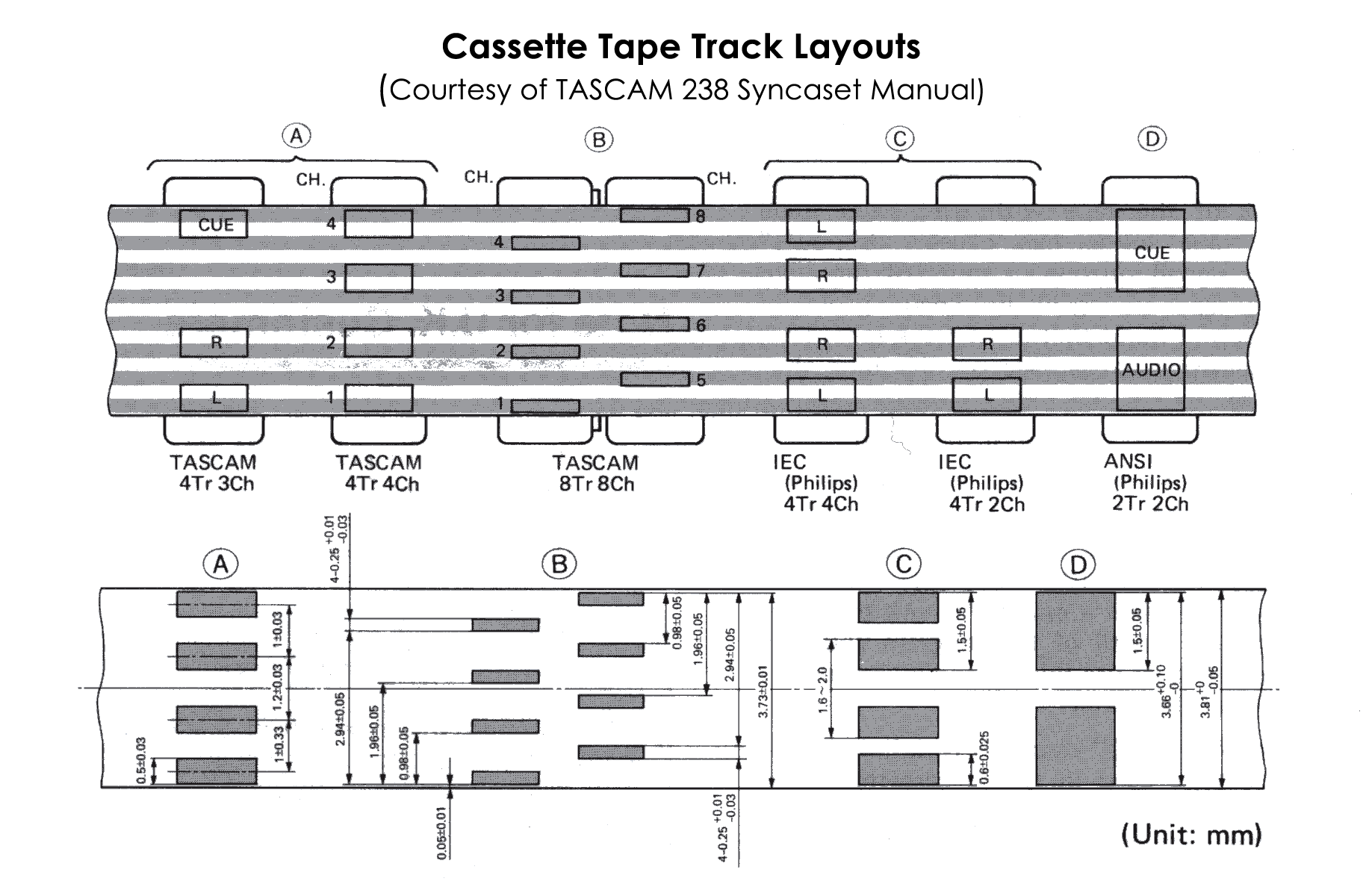
I have a TASCAM 4-tracks recorder that was using normal audio tapes.
As the tape width is the same, and also track position is similar, I
could try to move the tape from a TU58 cassette to an audio cassette,
then read it on the 4-tracks. The machine has a knob to adjust head
position slightly, so it could help.
I don' t remember if the speed of the tape could be adjusted too (maybe
normal / double).
Sampling the audio with a good sound card could give some good data to
be elaborated to extract data,
of course a filtering/recovery algorithm has to be developed (using
Matlab/Octave)?
If the procedure would prove to be working, I could offer my help to
image tapes, specially for 730 as they would be very useful
also to restore my machine (I really would like to have diagnostic tapes).
This procedure could work?
Andrea
> From: Al Kossow
> I just bought a big selection of difference sizes of Norprene tubing
> from US Plastics to see how they work on various QIC drives. The first
> ones I'm trying are the HP 9145 and TU58.
If/when we get our wiki up, the outcome of your work would be a great thing to
record there. (If you're too busy, I would be more than happy to scribe for
you!)
I, for instance, have a TU58 I'd like to get running some day, but given that
I have about 173 higher-priority things on the list in front of it, I'm sure
that by the time I get to it, I'll have some dim memory that it was talked
about here, but short of good luck with Google, or a voluminous search
through the archives, I won't be able to find what I need - and I'll have to
ask... :-( Had we all that kind of stuff in a wiki, on the other hand... :-)
Yes, not everyone will be diligent enough to check the wiki before they ask,
but hey, if they don't, you all can enjoy yourself flaming them for not being
willing to exert themselves to learn how to fish, before asking to just be
given some.. :-)
Noel
On 30 January 2015 at 23:43, js at cimmeri.com <js at cimmeri.com> wrote:
>
>
> On 1/30/2015 5:35 PM, Jules Richardson wrote:
>>
>>> And "whilst" I'm at it, why do some insist on using "blinkenlights" in re
>>> CPU front panels instead of correct English -- blinking lights?
>>
>>
>> Because it's mildly amusing.
>
>
> Maybe the first time it was... :)
It's not only that. It's because 'blinking lights' is generic, it
could mean anything. But 'blinkenlights'.. you'll *know* what it
means.
Here:
http://www.ebay.com/itm/141300893919
The seller has them listed at 'Buy-It-Now' for $1,800, but the listing does
say 'make an offer', so you might be able to get it down a ways, to something
more reasonable. They seem like they have an interesting (non-identical) set
of peripheral cards. However, I know nothing of HP's, so take this all with a
large grain of salt!
Noel
-----Original Message-----
>From: Noel Chiappa <jnc at mercury.lcs.mit.edu>
>Sent: Jan 30, 2015 5:19 AM
>To: cctalk at classiccmp.org
>Cc: jnc at mercury.lcs.mit.edu
>Subject: Re: strange number corruption on pdp11/34
>
> > From: Don North
>
> > So here is the octal print routine in the M9312 console boot prom for
> > the '34:
>
>I'm curious, is that the 'original' source, or is this dis-assembled from the
>PROM contents? Is the complete program available somewhere?
Disassembled and re-commented source. Available here:
http://ak6dn.dyndns.org/PDP-11/M9312/
along with most all of the other M9312 boot and device PROMS.
>
> > So I would speculate either 'rol' or 'rolb' are always rotating in a 0
> > bit instead of the c-bit, or possibly the c-bit is stuck at zero.
>
>Yup, good suggestion. And that would likely explain why things boot; I can't
>see too many OS's using 'ROLB'!
>
> Noel
>ODERWISE IST EASY TO SCHNAPPEN DER SPRINGENWERK, BLOWENFUSEN UND
POPPENCORKEN MIT SPITZENSPARKEN.
This is hilarious (particularly if you know German)! I didn't know about it,
thanks for posting! I'll hang it above my collection!
Marc
------------------
Because the Faux German Blinkenlights is so much cooler to say. It?s a
corruption of Blinenlichten from an old joke:
ACHTUNG!
ALLES TURISTEN UND NONTEKNISCHEN LOOKENPEEPERS!
DAS KOMPUTERMASCHINE IST NICHT F?R DER GEFINGERPOKEN UND MITTENGRABEN!
ODERWISE IST EASY TO SCHNAPPEN DER SPRINGENWERK, BLOWENFUSEN UND
POPPENCORKEN MIT SPITZENSPARKEN.
IST NICHT F?R GEWERKEN BEI DUMMKOPFEN. DER RUBBERNECKEN SIGHTSEEREN KEEPEN
DAS COTTONPICKEN H?NDER IN DAS POCKETS MUSS.
ZO RELAXEN UND WATSCHEN DER BLINKENLICHTEN.
which dates to the 1950?s?
See also the insistence on the plural of VAX being VAXEN.
Warner
-----------------
Has anyone used this software
ftp://minnie.tuhs.org/pub/PDP-11/Vtserver/README against a real pdp11? I'm
trying to use it to install a disk image on my 11/34, now, and after keying
in the initial code, it appears to happily upload the first file
(standalone 'copy') quite successfully, but then hangs. Since Warren has
no real pdp11s, I'm wondering if the emulators he used whilst authoring
this VTserver do something different than a real '11 that keeps the program
>from proceeding.
thx
jake
I've been working on a software emulation of the Extended Arithmetic
Element for the PDP-8/E. I've been struggling a little with the multiply
(MUY) instruction in particular.
I don't have an actual EAE to test this all with, but I'd appreciate anyone
with one to test out a bit of code to confirm.
In any event, both SimH and the OS X PDP-8/E Simulator exhibit the same
symptoms, which seem to multiply (PC + 1) by MQ and add AC, placing that
result into AC, MQ. Expected behavior, best I can tell from the Maintenance
Manual Volume 2, would be (PC + 1) * MQ -> AC, MQ, without the addition of
the previous AC prior to executing MUY. If this is the case, then clearing
AC would be essentially required, unless you want to add that value after
the multiply (which could be a useful mathematical operation in some
circumstances).
There is a little code found on bitsavers that seems to emulate these EAE
instructions:
http://bitsavers.trailing-edge.com/bits/DEC/pdp8/From_Vince_Slyngstad/digit…
You'll
note that there is no DCA at the top of the MUY subroutine to save AC in
order to add it to MQ (and complete the carry) afterward.
I've been writing a comparison tool after finding that one program changed
to support the software EAE failed to function correctly, hence attempting
to track down some differences.
If you're interested in trying on real hardware (which would be
appreciated), here's what I'm running:
MUY=7405
DVI=7407
NMI=7411
SHL=7413
ASR=7415
LSR=7417
MQL=7421
SCL=7403
SCA=7441
MQA=7501
CAM=CLA MQL
*200
CLA CLL
TAD MQVAL
MQL
TAD ACVAL
HLT
MUY
7777
HLT
MQVAL, 7777
ACVAL, 7777
$
After the first halt, AC=MQ=7777, as expected. After continuing, AC=7777,
MQ=0000. This would be equivalent to 7777*7777+7777=77770000, rather than
the expected value of 7777*7777=77760001.
Any help would greatly ease my concerns!
Kyle
> From: jws
> I sent a bit of this thread along to Ken Omohundro who founded Able ..
> If he sends anything else along, I'll get it to somewhere people can
> find out about it.
Neat! Thanks!
> I probably have data sheets archived and I will scan them as a PDF file
Those would be great - I hope they include enough detail to explain how the
ENABLE hooked up the various busses, cache, etc! I live in hope that someone
finds a manual, because that may be the only way these questions get answered.
Also, I wonder if the product called the "ENABLE/34" (per various brochures,
Muuss' email, etc) and the "ENABLE" we ran in the 11/45 were actually the same
thing, and they had just changed the name, perhaps because people might have
assumed, from the "ENABLE/34" name, that it was only for /34's, when in fact
it could run in any UNIBUS machine? The name change may have opened up a
bigger market for them. Anyway, another mystery about these things!
Noel
Woohoo, I finally, after over a decade of being somewhat out of the pdp11
hobby, have managed to bring back to life one of my pdp11/34s!
It's a plain 11/34 with dl11-w, ky11-lb, ms11-L, rl11 and a M9312
terminator/boot rom board. I have an emulex controller and some fuji 160s
I'll tack on later so I can run 2.9BSD once I get the basic build confirmed
safe.
It's not in great shape at the moment, apparently, as these xxdp 2.5 diags
are crashing left and right. But it at least boots the os and tries.
I initially had, but mysteriously lost the console emulator/ODT
functionality, seems it's starting at 165000 instead of 165200 at poweron.
Maybe a 9312 switch mis-set... So I'm booting from the panel by calling
the address of the ODT or the rl02 boot rom, which does the trick.
Would anyone care to recommend some xxdp diags I should be running or next
steps to isolate what's wrong / right with it?
thx
jake
P.S.
I tried to boot rsx11m v4.1, but got a strange crash with all zeroes in the
stack and registers. What might that indicate?
@DL0
DEVICE DD000: NOT IN CONFIGURATION
DEVICE DD100: NOT IN CONFIGURATION
DEVICE DY002: NOT IN CONFIGURATION
DEVICE DY102: NOT IN CONFIGURATION
MEVICE NI002: NOT IN CONFIGURATION
RSX-11M V4.1 BL35 124.K MAPPED
SYSTEM CRASH AT LOCATION 000000
REGISTERS
R0=000000 R1=000000 R2=000000 R3=000000
R4=000000 R5=000000 SP=000000 PS=000000
SYSTEM STACK DUMP
LOCATION CONTENTS
000000 000000
000000 000000
000000 000000
000000 000000
000000 000000
000000 000000
000000 000000
000000 000000
000000 000000
000000 000000
000000 000000
000000 000000
000000 000000
000000 000000
000000 000000
000000 000000
000000 000000
000000 000000
000000 000000
000000 000000
000000 000000
000000 000000
000000 000000
CRASH -- CONT WITH SCRATCH MEDIA ON DY0
I just can't seem to figure out the right XXDP file to run for a straight memory test.
I've got a new (for me) pdp11/23+ with M8044 memory boards, and I'd like to run memory tests, but I'm damned if I can figure out what, exactly, to run.
This is XXDP 2.5
Thanks for any advice.
> From: Don North
> So here is the octal print routine in the M9312 console boot prom for
> the '34:
I'm curious, is that the 'original' source, or is this dis-assembled from the
PROM contents? Is the complete program available somewhere?
> So I would speculate either 'rol' or 'rolb' are always rotating in a 0
> bit instead of the c-bit, or possibly the c-bit is stuck at zero.
Yup, good suggestion. And that would likely explain why things boot; I can't
see too many OS's using 'ROLB'!
Noel
There's a change to the keynote plans for VCF East.
Ted Nelson is unable to attend due to a family issue. He sends his
regrets, and said he'll try to make it up to us another time.
Wes Clark will take Ted's place on Saturday morning at the show.
We are looking for other speakers and/or entertainment for the Saturday
dinner (when Wes was scheduled to speak).
Details are frequently updated at http://www.vintage.org/2015/east.
- Evan
So here is the octal print routine in the M9312 console boot prom for the '34:
; print an octal number followed by one <SP>
;
; R0 = register value to print
; R1 = return address
; R2 = temp char
; R3 = temp addr
prtoct: mov #<'0/bit1>,r2 ; ascii 0 right 1b
sec ; shift a 1 into R0 lsb as done bit
1$: rol r0 ; msb out of R0
rolb r2 ; into lsb of R2
mov pc,r3 ; ret addr
br txchar ; print char in R2
mov #<BL*bit8>+200+<'0/bit3>,r2 ; ascii SP upper, ascii 0 right 3b lower
2$: asl r0 ; msb out of R0
beq 3$ ; when R0 has gone to zero we are done
rolb r2 ; into lsb of R2
bcs 2$ ; loop once more if flagbit was set
br 1$ ; go get last bit and print char
3$: swab r2 ; move the SP from upper byte to lower
mov pc,r3 ; ret addr
br txchar ; print the space char in R2
retR1: cmp (r1)+,(r1)+ ; bump return address ptr R1 by +4
jmp -2(r1) ; return to (R1)-2
So I would speculate either 'rol' or 'rolb' are always rotating in a 0 bit instead of the
c-bit, or possibly the c-bit is stuck at zero.
-----Original Message-----
>From: Jacob Ritorto <jacob.ritorto at gmail.com>
>Sent: Jan 29, 2015 7:08 PM
>To: "General Discussion: On-Topic and Off-Topic Posts" <cctalk at classiccmp.org>
>Subject: Re: strange number corruption on pdp11/34
>
>So, pardon the large post, but here's the real comparison between my
>'mysterious zero bug' KD11E-A cpu board M8266, and my good one: First is
>the bad. Note that even at power on, I have to halt and restart the
>console emulator at 165200. Look at the registers, all blanked to zeroes
>and missing digits, too. It did manage to boot xxdp, but when I tried to
>enter the correct address and vector to ZRLG??, it actually told me I was
>wrong and couldn't even run the test on the device that way. Then I just
>accepted the default (which was presented as zeroes) and it did run. Two
>passes. Blinking lights and audible head movement. I let it run for two
>passes, but it presented even that as zero passes and spit a bunch of
>zeroes in the results. Just for kicks, I then booted (and very promptly
>crashed) RSX. It crash-dumped, giving a whole lot of zeroes. Next post
>will be same test with the good KD11E-A; stay tuned..
>
>thx
>jake
>
>
>?@
>000000 000 00000 000000
>@
>0 000 00000 00000
>@
>0 000 00000 00000
>@
>0 000 00000 00000
>@
>0 000 00000 00000
>@
>0 000 00000 00000
>@DL?
>
>
>BOOTING UP XXDP-XM EXTENDED MONITOR
>
>
>XXDP-XM EXTENDED MONITOR - XXDP V2.5
>REVISION: F0
>BOOTED FROM DL0
>124KW OF MEMORY
>UNIBUS SYSTEM
>
>RESTART ADDRESS: 152000
>TYPE "H" FOR HELP !
>
>.R ?RLG??
>NRLGA0.BIC
>
>DRSSM-G2
>CNRLG-A-0
>CNRLG TESTS CONTROLLER FUNCTIONS, INTERFACE LOGIC, REGISTER OPERATION
>UNIT IS RL01,RL02
>RSTRT ADR 000000
>DR>START
>
>CHANGE HW (L) ? Y
>
># UNITS (D) ? 1
>
>UNIT 0
>RL11=1, RLV11=2, RLV12=3 (O) 0 ? 1
>BUS ADDRESS (O) 0 ? 174400
>
># TOO LARGE
>BUS ADDRESS (O) 0 ? 174400
>
># TOO LARGE
>BUS ADDRESS (O) 0 ?
>VECTOR (O) 0 ? 160
>
># TOO LARGE
>VECTOR (O) 0 ?
>
>TOO MANY VALUES INPUT
>VECTOR (O) 0 ?
>DRIVE (O) 0 ?
>DRIVE TYPE = RL01 (L) Y ? N
>BR LEVEL (O) 0 ? 5
>
>CHANGE SW (L) ? N
>
>NXT TST MAY ZERO LD UNIT. DOIT ANYWAY?Y
>
>
> ILL INTER 000
> PC 000000 PS 000000
>DR>START
>
>CHANGE HW (L) ? Y
>
># UNITS (D) ?
>
>NO DEFAULT
># UNITS (D) ? 1
>
>UNIT 0
>RL11=1, RLV11=2, RLV12=3 (O) 0 ? 1
>BUS ADDRESS (O) 0 ?
>VECTOR (O) 0 ?
>DRIVE (O) 0 ?
>DRIVE TYPE = RL01 (L) Y ? N
>BR LEVEL (O) 0 ?
>
>CHANGE SW (L) ? N
>
>NXT TST MAY ZERO LD UNIT. DOIT ANYWAY?Y
>
>CNRLG DVC FTL ERR 00000 ON UNIT 00 TST 000 SUB 000 PC: 000000
>BAD SEEK-TEST OF DIFFENCE WORD
>CONTROLLER: 000000 DRIVE: 0
>BEFORE COMMAND: CS: 000000 BA: 000000 DA: 000000 MP: 000000
>TIME OF ERROR: CS: 000000 BA: 000000 DA: 000000 MP: 000000?
>LAST: 000000 PRES: 000000 EXP'D: 000000
>
>CNRLG DVC FTL ERR 00000 ON UNIT 00 TST 000 SUB 000 PC: 000000
>BAD SEEK-TEST OF DIFFENCE WORD
>CONTROLLER: 000000 DRIVE: 0
>BEFORE COMMAND: CS: 000000 BA: 000000 DA: 000000 MP: 000000
>TIME OF ERROR: CS: 000000 BA: 000000 DA: 000000 MP: 000000?
>LAST: 000000 PRES: 000000 EXP'D: 000000
>
>CNRLG DVC FTL ERR 00000 ON UNIT 00 TST 000 SUB 000 PC: 000000
>BAD SEEK-TEST OF DIFFENCE WORD
>CONTROLLER: 000000 DRIVE: 0
>BEFORE COMMAND: CS: 000000 BA: 000000 DA: 000000 MP: 000000
>TIME OF ERROR: CS: 000000 BA: 000000 DA: 000000 MP: 000000?
>LAST: 000000 PRES: 000000 EXP'D: 000000
>
>CNRLG DVC FTL ERR 00000 ON UNIT 00 TST 000 SUB 000 PC: 000000
>BAD SEEK-TEST OF DIFFENCE WORD
>CONTROLLER: 000000 DRIVE: 0
>BEFORE COMMAND: CS: 000000 BA: 000000 DA: 000000 MP: 000000
>TIME OF ERROR: CS: 000000 BA: 000000 DA: 000000 MP: 000000?
>LAST: 000000 PRES: 000000 EXP'D: 000000
>
>CNRLG DVC FTL ERR 00000 ON UNIT 00 TST 000 SUB 000 PC: 000000
>BAD SEEK-TEST OF DIFFENCE WORD
>CONTROLLER: 000000 DRIVE: 0
>BEFORE COMMAND: CS: 000000 BA: 000000 DA: 000000 MP: 000000
>TIME OF ERROR: CS: 000000 BA: 000000 DA: 000000 MP: 000000?
>LAST: 000000 PRES: 000000 EXP'D: 000000
>
>CNRLG DVC FTL ERR 00000 ON UNIT 00 TST 000 SUB 000 PC: 000000
>BAD SEEK-TEST OF DIFFENCE WORD
>CONTROLLER: 000000 DRIVE: 0
>BEFORE COMMAND: CS: 000000 BA: 000000 DA: 000000 MP: 000000
>TIME OF ERROR: CS: 000000 BA: 000000 DA: 000000 MP: 000000?
>LAST: 000000 PRES: 000000 EXP'D: 000000
>
>CNRLG DVC FTL ERR 00000 ON UNIT 00 TST 000 SUB 000 PC: 000000
>BAD SEEK-TEST OF DIFFENCE WORD
>CONTROLLER: 000000 DRIVE: 0
>BEFORE COMMAND: CS: 000000 BA: 000000 DA: 000000 MP: 000000
>TIME OF ERROR: CS: 000000 BA: 000000 DA: 000000 MP: 000000?
>LAST: 000000 PRES: 000000 EXP'D: 000000
>
>CNRLG DVC FTL ERR 00000 ON UNIT 00 TST 000 SUB 000 PC: 000000
>BAD SEEK-TEST OF DIFFENCE WORD
>CONTROLLER: 000000 DRIVE: 0
>BEFORE COMMAND: CS: 000000 BA: 000000 DA: 000000 MP: 000000
>TIME OF ERROR: CS: 000000 BA: 000000 DA: 000000 MP: 000000?
>LAST: 000000 PRES: 000000 EXP'D: 000000
>
>CNRLG DVC FTL ERR 00000 ON UNIT 00 TST 000 SUB 000 PC: 000000
>BAD SEEK-TEST OF DIFFENCE WORD
>CONTROLLER: 000000 DRIVE: 0
>BEFORE COMMAND: CS: 000000 BA: 000000 DA: 000000 MP: 000000
>TIME OF ERROR: CS: 000000 BA: 000000 DA: 000000 MP: 000000?
>LAST: 000000 PRES: 000000 EXP'D: 000000
>
>CNRLG DVC FTL ERR 00000 ON UNIT 00 TST 000 SUB 000 PC: 000000
>BAD SEEK-TEST OF DIFFENCE WORD
>CONTROLLER: 000000 DRIVE: 0
>BEFORE COMMAND: CS: 000000 BA: 000000 DA: 000000 MP: 000000
>TIME OF ERROR: CS: 000000 BA: 000000 DA: 000000 MP: 000000?
>LAST: 000000 PRES: 000000 EXP'D: 000000
>
>CNRLG DVC FTL ERR 00000 ON UNIT 00 TST 000 SUB 000 PC: 000000
>BAD SEEK-TEST OF DIFFENCE WORD
>CONTROLLER: 000000 DRIVE: 0
>BEFORE COMMAND: CS: 000000 BA: 000000 DA: 000000 MP: 000000
>TIME OF ERROR: CS: 000000 BA: 000000 DA: 000000 MP: 000000?
>LAST: 000000 PRES: 000000 EXP'D: 000000
>
>CNRLG DVC FTL ERR 00000 ON UNIT 00 TST 000 SUB 000 PC: 000000
>BAD SEEK-TEST OF DIFFENCE WORD
>CONTROLLER: 000000 DRIVE: 0
>BEFORE COMMAND: CS: 000000 BA: 000000 DA: 000000 MP: 000000
>TIME OF ERROR: CS: 000000 BA: 000000 DA: 000000 MP: 000000?
>LAST: 000000 PRES: 000000 EXP'D: 000000
>
>CNRLG EOP 0
> 0 TOTAL ERRS
>
>CNRLG DVC FTL ERR 00000 ON UNIT 00 TST 000 SUB 000 PC: 000000
>BAD SEEK-TEST OF DIFFENCE WORD
>CONTROLLER: 000000 DRIVE: 0
>BEFORE COMMAND: CS: 000000 BA: 000000 DA: 000000 MP: 000000
>TIME OF ERROR: CS: 000000 BA: 000000 DA: 000000 MP: 000000?
>LAST: 000000 PRES: 000000 EXP'D: 000000
>
>CNRLG DVC FTL ERR 00000 ON UNIT 00 TST 000 SUB 000 PC: 000000
>BAD SEEK-TEST OF DIFFENCE WORD
>CONTROLLER: 000000 DRIVE: 0
>BEFORE COMMAND: CS: 000000 BA: 000000 DA: 000000 MP: 000000
>TIME OF ERROR: CS: 000000 BA: 000000 DA: 000000 MP: 000000?
>LAST: 000000 PRES: 000000 EXP'D: 000000
>
>CNRLG DVC FTL ERR 00000 ON UNIT 00 TST 000 SUB 000 PC: 000000
>BAD SEEK-TEST OF DIFFENCE WORD
>CONTROLLER: 000000 DRIVE: 0
>BEFORE COMMAND: CS: 000000 BA: 000000 DA: 000000 MP: 000000
>TIME OF ERROR: CS: 000000 BA: 000000 DA: 000000 MP: 000000?
>LAST: 000000 PRES: 000000 EXP'D: 000000
>
>CNRLG DVC FTL ERR 00000 ON UNIT 00 TST 000 SUB 000 PC: 000000
>BAD SEEK-TEST OF DIFFENCE WORD
>CONTROLLER: 000000 DRIVE: 0
>BEFORE COMMAND: CS: 000000 BA: 000000 DA: 000000 MP: 000000
>TIME OF ERROR: CS: 000000 BA: 000000 DA: 000000 MP: 000000?
>LAST: 000000 PRES: 000000 EXP'D: 000000
>
>CNRLG DVC FTL ERR 00000 ON UNIT 00 TST 000 SUB 000 PC: 000000
>BAD SEEK-TEST OF DIFFENCE WORD
>CONTROLLER: 000000 DRIVE: 0
>BEFORE COMMAND: CS: 000000 BA: 000000 DA: 000000 MP: 000000
>TIME OF ERROR: CS: 000000 BA: 000000 DA: 000000 MP: 000000?
>LAST: 000000 PRES: 000000 EXP'D: 000000
>
>CNRLG DVC FTL ERR 00000 ON UNIT 00 TST 000 SUB 000 PC: 000000
>BAD SEEK-TEST OF DIFFENCE WORD
>CONTROLLER: 000000 DRIVE: 0
>BEFORE COMMAND: CS: 000000 BA: 000000 DA: 000000 MP: 000000
>TIME OF ERROR: CS: 000000 BA: 000000 DA: 000000 MP: 000000?
>LAST: 000000 PRES: 000000 EXP'D: 000000
>
>CNRLG DVC FTL ERR 00000 ON UNIT 00 TST 000 SUB 000 PC: 000000
>BAD SEEK-TEST OF DIFFENCE WORD
>CONTROLLER: 000000 DRIVE: 0
>BEFORE COMMAND: CS: 000000 BA: 000000 DA: 000000 MP: 000000
>TIME OF ERROR: CS: 000000 BA: 000000 DA: 000000 MP: 000000?
>LAST: 000000 PRES: 000000 EXP'D: 000000
>
>CNRLG DVC FTL ERR 00000 ON UNIT 00 TST 000 SUB 000 PC: 000000
>BAD SEEK-TEST OF DIFFENCE WORD
>CONTROLLER: 000000 DRIVE: 0
>BEFORE COMMAND: CS: 000000 BA: 000000 DA: 000000 MP: 000000
>TIME OF ERROR: CS: 000000 BA: 000000 DA: 000000 MP: 000000?
>LAST: 000000 PRES: 000000 EXP'D: 000000
>
>CNRLG DVC FTL ERR 00000 ON UNIT 00 TST 000 SUB 000 PC: 000000
>BAD SEEK-TEST OF DIFFENCE WORD
>CONTROLLER: 000000 DRIVE: 0
>BEFORE COMMAND: CS: 000000 BA: 000000 DA: 000000 MP: 000000
>TIME OF ERROR: CS: 000000 BA: 000000 DA: 000000 MP: 000000?
>LAST: 000000 PRES: 000000 EXP'D: 000000
>
>CNRLG DVC FTL ERR 00000 ON UNIT 00 TST 000 SUB 000 PC: 000000
>BAD SEEK-TEST OF DIFFENCE WORD
>CONTROLLER: 000000 DRIVE: 0
>BEFORE COMMAND: CS: 000000 BA: 000000 DA: 000000 MP: 000000
>TIME OF ERROR: CS: 000000 BA: 000000 DA: 000000 MP: 000000?
>LAST: 000000 PRES: 000000 EXP'D: 000000
>
>CNRLG DVC FTL ERR 00000 ON UNIT 00 TST 000 SUB 000 PC: 000000
>BAD SEEK-TEST OF DIFFENCE WORD
>CONTROLLER: 000000 DRIVE: 0
>BEFORE COMMAND: CS: 000000 BA: 000000 DA: 000000 MP: 000000
>TIME OF ERROR: CS: 000000 BA: 000000 DA: 000000 MP: 000000?
>LAST: 000000 PRES: 000000 EXP'D: 000000
>
>CNRLG DVC FTL ERR 00000 ON UNIT 00 TST 000 SUB 000 PC: 000000
>BAD SEEK-TEST OF DIFFENCE WORD
>CONTROLLER: 000000 DRIVE: 0
>BEFORE COMMAND: CS: 000000 BA: 000000 DA: 000000 MP: 000000
>TIME OF ERROR: CS: 000000 BA: 000000 DA: 000000 MP: 000000?
>LAST: 000000 PRES: 000000 EXP'D: 000000
>
>CNRLG DVC FTL ERR 00000 ON UNIT 00 TST 000 SUB 000 PC: 000000
>BAD SEEK-TEST OF DIFFENCE WORD
>CONTROLLER: 000000 DRIVE: 0
>BEFORE COMMAND: CS: 000000 BA: 000000 DA: 000000 MP: 000000
>TIME OF ERROR: CS: 000000 BA: 000000 DA: 000000 MP: 000000?
>LAST: 000000 PRES: 000000 EXP'D: 000000
>
>CNRLG DVC FTL ERR 00000 ON UNIT 00 TST 000 SUB 000 PC: 000000
>BAD SEEK-TEST OF DIFFENCE WORD
>CONTROLLER: 000000 DRIVE: 0
>BEFORE COMMAND: CS: 000000 BA: 000000 DA: 000000 MP: 000000
>TIME OF ERROR: CS: 000000 BA: 000000 DA: 000000 MP: 000000?
>LAST: 000000 PRES: 000000 EXP'D: 000000
>
>CNRLG DVC FTL ERR 00000 ON UNIT 00 TST 000 SUB 000 PC: 000000
>BAD SEEK-TEST OF DIFFENCE WORD
>CONTROLLER: 000000 DRIVE: 0
>BEFORE COMMAND: CS: 000000 BA: 000000 DA: 000000 MP: 000000
>TIME OF ERROR: CS: 000000 BA: 000000 DA: 000000 MP: 000000?
>LAST: 000000 PRES: 000000 EXP'D: 000000
>
>CNRLG EOP 0
> 0 TOTAL ERRS
>^C
>DR>^C^C
>DR>
>XIT^U
>EXIT
>?@
>000000 000 00000 000000
>@
>0 000 00000 00000
>@
>0 000 00000 00000
>@
>0 000 00000 00000
>@DL?
> DEVICE DD000: NOT IN CONFIGURATION
>DEVICE DD100: NOT IN CONFIGURATION
>DEVICE DY002: NOT IN CONFIGURATION
>DEVICE DY102: NOT IN CONFIGURATION
>DEVICE NI002: NOT IN CONFIGURATION
>
> RSX-11M V4.1 BL35 124.K MAPPED
>
>SYSTEM CRASH AT LOCATION 000000
>
>REGISTERS
>
> R0=000000 R1=000000 R2=000000 R3=000000
>
> R4=000000 R5=000000 SP=000000 PS=000000
>
>SYSTEM STACK DUMP
>
> LOCATION CONTENTS
>
> 000000 000000
> 000000 000000
> 000000 000000
> 000000 000000
> 000000 000000
> 000000 000000
> 000000 000000
> 000000 000000
> 000000 000000
> 000000 000000
> 000000 000000
> 000000 000000
> 000000 000000
> 000000 000000
> 000000 000000
> 000000 000000
> 000000 000000
> 000000 000000
> 000000 000000
> 000000 000000
> 000000 000000
> 000000 000000
> 000000 000000
>
>
>CRASH -- CONT WITH SCRATCH MEDIA ON DY0
>
>On Thu, Jan 29, 2015 at 9:30 PM, Jacob Ritorto <jacob.ritorto at gmail.com>
>wrote:
>
>> ok, now with my 'good' 11/34 board set (not the set with the mysterious
>> zero bug) installed, I re-ran xxdp against the rl02. I'm getting proper
>> prompts with the address and vectors supplied with non-zero numbers as
>> defaults. I just hit return like I had been doing with the 'zero-bug' cpu
>> boards and this time, the tests run, the drive blinks wildly like before,
>> and I get real results with real numbers filled in. I think this pretty
>> conclusively proves that there's something really weird (mysterious zero
>> bug) going on with my other board set.
>>
>> On Thu, Jan 29, 2015 at 7:15 PM, Johnny Billquist <bqt at update.uu.se>
>> wrote:
>>
>>> On 2015-01-29 20:14, Pete Turnbull wrote:
>>>
>>>> On 29/01/2015 18:32, Jacob Ritorto wrote:
>>>>
>>>>> Johnny, you're insisting that I put in the real numbers for address
>>>>> and csr
>>>>> for testing the drive (for instance). I'm going to do that next, here.
>>>>> But are you understanding that some of us think that the reason it
>>>>> prompts
>>>>> a zero default is that it's a manifestation of the zero bug and that the
>>>>> real value *is* actually safe but hidden in memory? Did you see the
>>>>> RSX-11M crash dump I posted in the other thread?
>>>>>
>>>>
>>>> I didn't see a crash dump, but did you see what I posted yesterday?
>>>>
>>>
>>> I haven't seen any crash dumps either.
>>>
>>> The default in XXDP for CSRs is very often zero, and I'm pretty sure it
>>>> is so in the RL02 diagnostics (I've ont checked the listing for that
>>>> particular one, but I did look at some others that were more readily to
>>>> hand). So when it asked you for input and you just hit "return", you
>>>> really did tell it zero. Applying the principle of Occam's Razor, and
>>>> assuming the simplest solution is the correct one, you got a lot of
>>>> zeros back because it was accessing memory instead of the controller you
>>>> wanted.
>>>>
>>>> It's hard to believe you have a CPU fault that consistently prints
>>>> numbers as zeros yet happily boots three different OSs. Still, I'll
>>>> change the tune if you re-run XXDP with sensible inputs.
>>>>
>>>
>>> Totally agree with that one.
>>>
>>>
>>> Johnny
>>>
>>> --
>>> Johnny Billquist || "I'm on a bus
>>> || on a psychedelic trip
>>> email: bqt at softjar.se || Reading murder books
>>> pdp is alive! || tryin' to stay hip" - B. Idol
>>>
>>
>>
So, I'm in the process of trying to read those old MIT V6 Unix dump tapes
(with a really big hand from Chuck, who did all the ugly work of actually
reading the bits off the tapes, for which he has my undying gratitude!), and
although I'm still trying to figure out what the format is, I did manage to
retrieve, more or less, a copy of the assembler startup/support file (m47.s; a
hacked version of m45.s), and it reveals that we were using an Able ENABLE
card to take our 11/45 out to more than 256KB.
I found a copy of brochure which very briefly describes/shows it here:
http://archive.org/stream/bitsavers_ablebrochuuctSummary_2920347/Able_Compu…
and although the picture didn't ring any bells for me, that must be it.
It looks like it has a UNIBUS connector (which I take it is 'UNIBUS out'), and
also some kind of 'over-the-back' connector which I assume is the bus to the
memory, which sounds (from a brief mention I found somewhere else) like it was
standard Extended UNIBUS memory in a separate backplane. (Although I could be
wrong; maybe the ENABLE plugged into the EUB backplane, and the UNIBUS
connector is 'UNIBUS in' from the CPU?)
I was unable to locate any real documentation for it online (maybe my
Google-fu just isn't strong enough), but if someone has any, or can point me
at any, I'd be grateful.
Any if anyone actually has one, in the flesh, that would be Really Cool!
Noel
At 07:34 PM 1/27/2015, Jacob Ritorto wrote:
>Johnny, I just took the defaults,
>BUS ADDRESS (O) 0 ?
What Johnny said. The prompt says "(O)", not "(0)" - the letter O for
Octal. The zero after that isn't a default, it simply means that the
value hasn't been set.
There is no default. Or at least no sane one. Zero in this case means
that it's writing to memory address zero for CSR. The diagnostic should
reject that, but diagnostics are notoriously user unfriendly.
-Rick
For those of you who are Spacewar! buffs and you haven't seen Norbert
Landsteiner's work, you are missing something big.
Norbert has what I believe to be the best simulation of original PDP-1
Spacewar! code running on a Model 30 display. And he doesn't just have
one version Spacewar! - but several original versions.
In addition, Norbert analyzed the original Spacewar! code line-by-line
and created an incredible set of writeups on Spacewar! internals.
As Norbert created his writeups, he sent them to me. I read them over,
and forwarded them to the entire PDP-1 Team at the Computer History
Museum. That Team includes Steve Russell (principal author of
Spacewar!) and Peter Samson (Spacewar! star field, etc.).
Additionally, I met with both Steve and Peter and we reviewed
several of Norbert's writeups together in some detail - and found only a
few minor corrections/comments to pass back to Norbert.
Here are links to Norbert's work:
Simulation
----------
http://www.masswerk.at/spacewar/
Writeups (Inside Spacewar!)
---------------------------
http://www.masswerk.at/spacewar/inside/
Cheers,
Lyle
--
Bickley Consulting West Inc.
http://bickleywest.com
"Black holes are where God is dividing by zero"
> From: Roe Peterson
> How is it that googling
> XXDP manual
> XXDP documentation
> XXDP memory test
> Doesn't point at this?
Because Googling, useful as it is, is inferior to humans^H^H^H intelligences
actually sorting things out, and organizing them in a structured manner. (The
way Yahoo worked when it very first started...)
Now, if we had a wiki.... :-)
Noel
> From: Jacob Ritorto
> I just need quite a lot of hand holding because I'm still way too green
> with this stuff.
Hey, that's what this list is for, right? ;-)
> put in the real numbers for address and csr for testing the drive ...
> I'm going to do that next, here. ... the reason it prompts a zero
> default is that it's a manifestation of the zero bug and that the real
> value *is* actually safe but hidden in memory?
One other thing you could do that would be interesting: re-run the exact
same test, but with the good cards in the machine, and see if you still
get 0's printed, or if this time the correct numbers show up.
Of course, that won't definitely prove that the right numbers are actually
being used inside (in the case where it prints 0's), but it would certainly be
suggestive.
Noel
>Alexandre Souza wrote:
> ----- Original Message ----- From: "Mark J. Blair" <nf6x at nf6x.net>
> To: "General Discussion: On-Topic and Off-Topic Posts"
> <cctalk at classiccmp.org>
> Sent: Tuesday, January 27, 2015 3:04 PM
> Subject: Destructive Imaging of DECTAPE II Media
>
> [Snip]
>
> What do you folks think about this silliness?
It has been over 2 years since I last used my TU58 tape drive,
but it was still working then with (of course USABLE) TU58
tapes, although a good percentage were no longer in that
category. If it seems reasonable, I can try to see if the TU58
tape drive will still function correctly.
If the TU58 tapes which need to be recovered can still be
read by a TU58 drive, then I could undertake to recover
those ones. Note that I am in Toronto, so postage would
be MUCH more than within the US.
Unfortunately, there is no visual difference between tapes
which can still be read and those which have errors that
can't be recovered. But if the tape can't even be moved
or the drive belt is broken, either of those problems would
prevent a standard DEC TU58 drive from being able to
recover any data from the tape.
Jerome Fine
> From: Johnny Billquist
> I searched around a bit more today.
> I did find a couple of brochures on bitsavers that mentions it.
Err, you didn't need Google for that - the first post in this thread
mentioned it... :-)
>> Standard Extended UNIBUS (a la 11/24 and 11/44), I think.
> "Standard" is a strong word here. :-)
Well, 'standard' in the sense that more than one DEC machine used it, and one
could buy third-party memory cards that conformed to it.
> The Megabox .. As far as I know, it is not a Unibus at all. And it
> still could not be a Unibus, for the same reason I mentioned above.
I _suspect_ that internally it has a backplane which supported EUB, and the
memory plugged into that; whether that was a custom backplane, or what, I
don't know. (I'd have to check the wire-lists on, say, a DD11-D to see if
those pins are bussed together - I have this vague memory that they are.)
And yes, _iff_ the cable to it is a standard UNIBUS cable (I don't know what
kind of cable they used), that would only support the 18-bit address space -
which would imply that the ENABLE card was in the Megabox.
>> (And I can show you the code... :-) The original MMU was retained; the
>> ENABLE included only a second set of PARS (full 16-bit wide), which
>> were the ones normally used while the system was running; the PDRs in
>> the CPU continued to be used as the _only_ PDRs in the system.
> That would imply you could not address more than 256K from the CPU. Not
> likely...
Dude, I PERSONALLY WROTE THE CODE TO USE THE ENABLE. And I have the source,
here:
http://ana-3.lcs.mit.edu/~jnc/tech/unix/mit/conf/m47.s
You are correct, the CPU cannot _directly_ address more than 256KB. However,
the ENABLE board _can_; mapping registers in the ENABLE (32 of them, each
handling an 8KB section of incoming UNIBUS address space, from the CPU) allow
that UNIBUS address space to be mapped, in 8KB blocks, anywhere in the 22-bit
memory space.
You will find it all laid out most ably in this old post by Mike Muuss
(peace, Mike):
http://gopher.quux.org:70/Archives/usenet-a-news/FA.unix-wizards/81.07.12_u…
It looks like I used a slightly different layout of the address space on the
UNIBUS from the CPU to the ENABLE from the one he describes (the code in
m47.s seems to use:
KI0-7
KD0-6
UI0-7
UD0-7
KD7 I/O page
with the KI underneath the KD, unlike his; KD7 has to be at the top so that
the CPU can get to the registers in the ENABLE), but other than that the
details are identical. (Note that they only differ in how the registers were
_used_, not in terms of what the hardware's capabilities were.)
>> The style of usage was to, using the CPU's PARs, statically map Kernel
>> D space to one quadrant of UNIBUS address space, Kernel I to a second,
>> User D to a third, and User I to the fourth.
> The 11/34 do not have D-space...
I was talking about on the /45.
>> The PARs on the ENABLE card (which controlled which part of real
>> memory various addresses on the first UNIBUS got mapped to) were the
>> ones the operating system adjusted as the system was running.
> Sorry, this is simply not how it worked.
Repeat previous comment about how I personally wrote the code to use it.
Just for you, I have groveled around in the dump I'm working on retrieving,
and found seg.h, which is the header file which contains the #defines for the
mapping registers in Unix V6. Here it is:
http://ana-3.lcs.mit.edu/~jnc/tech/unix/mit/h/seg.h
If you look at it, you will see that UISA[0] has been modified to be
"0163736". That's how we did the ENABLE - we just changed those definitions,
and recompiled all the system modules that touched the mapping registers, so
that that code now talked to the 16-bit PARs on the ENABLE, and not the
12-bit ones in the KT (which were set once at system startup time to provide
the static mapping - see m47.s - and then never changed again).
> Like I said, I actually used an 11/34 with the ENable/34 and the
> separate memory box for a few years. It really looked and behaved
> identically to an 11/24. Ie, full 16-bit PARs, still no split I/D space.
Yes, no split I/D because it was totally external to the CPU, it could only
take the UNIBUS addresses the CPU generated and map them around.
>> I'm kind of hazy on exactly how this was all wired up: there are the
>> fingers on the card (which I think _might_ be the EUB used for the
>> memory bus), the UNIBUS edge connector on the ENABLE card, and that
>> over-the-back connector on the ENABLE card.
> An 11/34 do not have any EUB slots.
I was assuming that the ENABLE used an EUB to talk to its memory. (See
diagram further up the original post.)
> (You should see Updates storage rooms...)
Even better would be being allowed to poke around in there... :-)
> I was running RSX-11M and RSX-11M-PLUS on our 11/34, and no
> modifications to the kernel was needed.
There must have been some changes somewhere, since as you can see from the
code above, the ENABLE had PARs in non-standard locations (0163700-0163776).
Anyway, if you could find the documentation that would be super-wonderful,
because I am _really_ curious to know exactly how the thing interfaced to the
incoming UNIBUS, outgoing UNIBUS, memory, and cache.
Noel
On 25 January 2015 at 00:04, John Foust <jfoust at threedee.com> wrote:
> I haven't ever played with official Sugru, but how does it differ
> from ordinary relatively inexpensive Shoe Goo? Is Sugru like
> slightly dried-out Shoe Goo? I find that a tube of Shoe Goo
> dries out a bit after a few years and becomes a more easily worked
> substance.
I've never heard of this Shoe Goo stuff before, so I can't comment on
a direct comparison.
I've used a differently-branded Sugru alternative, though. It's not an
adhesive and it's not sticky. It's like Plasticine or other modelling
clay -- a smooth, non-tacky, very viscous colloidal gel, which can be
moulded and shaped. It only adheres to things by virtue of being
moulded onto and around them; if you need to, say, stick it to a flat
surface, you'd have to glue it on.
But when it sets, it goes hard - like a hard rubber. You can make a
small mark with a fingernail but this will eventually smooth out. It's
no more pliable than a piece of truck tyre when cured.
--
Liam Proven ? Profile: http://lproven.livejournal.com/profile
Email: lproven at cix.co.uk ? GMail/G+/Twitter/Flickr/Facebook: lproven
MSN: lproven at hotmail.com ? Skype/AIM/Yahoo/LinkedIn: liamproven
Cell/Mobiles: +44 7939-087884 (UK) ? +420 702 829 053 (?R)
> From: Johnny Billquist
> However, the was one board that went into the CPU box, and then there
> was a cable or two out from that to a separate memory box that held the
> memory. So the memory cards themself was not in the CPU box
Right, that's a product called the Megabox; details I can find online about
it are thin, but it seems to include the Extended UNIBUS backplane the memory
sits on, and the memory cards. (Google 'ABLE Enable Megabox' and it'll pop up
a short Computerworld blurb about it.)
> The machines that had more than 256K of memory, and were Unibus based,
> and had the memory on the "unibus" actually had a special backplane for
> the memory cards, where otherwise unused signals were used to do the
> extra addressing bits.
Standard Extended UNIBUS (a la 11/24 and 11/44), I think.
> Which also means that all the memory cards had to sit in the same
> backplane as the CPU. They could not be put in any other Unibus
> backplane.
Anyway, no, the memory did not have to be in the same backplane as the CPU;
see the Megabox, where the memory was in that box.
However, a caveat: there is some possibility there was more than one version
of the ENABLE, in which case two seemingly contradictory statements about
'the' ENABLE might in fact both be correct. But until that's shown, let's
assume there's only one kind... :-)
The thing that I think did have to be on (in, actually - see below) the main
UNIBUS was the ENABLE card. I think the logical configuration was like this
(diagram semi-ripped off from Mike Muuss' email):
Processor ---------- ENABLE ------------------------ Term.
UNIBUS | | UNIBUS
| EUB |
| |
|_ 11/44 style |
memory |_ Devices (both DMA and
non-DMA)
I think all the devices - well, you could have put non-DMA devices on the
section between the CPU and the ENABLE - all DMA devices at least, had to be
on the second UNIBUS, because the ENABLE included a UNIBUS map, which was
separate from the PARs used for CPU accesses, so I think that's pretty
conclusive that the CPU and DMA devices did not share a UNIBUS.
> and you'll get a new MMU which implements all the bits in the PAR
> registers. ..
> So, it also implies that the original MMU have to be removed.
No. (And I can show you the code... :-) The original MMU was retained; the
ENABLE included only a second set of PARS (full 16-bit wide), which were the
ones normally used while the system was running; the PDRs in the CPU
continued to be used as the _only_ PDRs in the system.
The style of usage was to, using the CPU's PARs, statically map Kernel D
space to one quadrant of UNIBUS address space, Kernel I to a second, User D
to a third, and User I to the fourth. (You wanted to use Supervisor mode too?
Thhhppptttt!) Those mappings would be on the segment between the CPU and
ENABLE; once initially set up, those mappings (i.e. CPU PAR contents) were
never changed.
The PARs on the ENABLE card (which controlled which part of real memory
various addresses on the first UNIBUS got mapped to) were the ones the
operating system adjusted as the system was running.
> And that is where you put the new card in.
I don't think so.
I'm kind of hazy on exactly how this was all wired up: there are the fingers
on the card (which I think _might_ be the EUB used for the memory bus), the
UNIBUS edge connector on the ENABLE card, and that over-the-back connector on
the ENABLE card. Then there were 4 things that had to be connected up: the
CPU UNIBUS, the memory EUB, the device UNIBUS, and an optional cache memory
card ... but we have only three connectors. So whether the cache somehow hung
off the EUB, or directly from the ENABLE via a custom backplane, or what, I'm
not sure.
> I don't know anything about the 11/45 extension this way. Like I said,
> I only played with an 11/34 that had this.
Anything you could do on the /34 could of course also be done on the /45
(since the ENABLE did not involve any mods to the CPU, it just interfaced to
the UNIBUS).
Although I have this bit set that perhaps it - or, one variant of the ENABLE
(see comment above about more than one) - somehow used the fast memory slots
in the 11/45 backplane (originally designed for special high-speed solid
state memory) and that's how you got full advantage of the cache. (I have
this distinct memory of running 'mips' on our /45 after it was upgraded and
the result was '3'...) But probably something in my memory is flaky - it was
a long time ago.
> I probably should try to find the documentation for exact details here
> then. I might be able to track down the machine, but I haven't seen it
> in almost 20 years.
If you could track down the documentation, that would be really good.
The programming of the thing we can work out (in addition to my code for V6
Unix, there is code online for other versions of Unix which support it, e.g.
BSD2.9). It's the physical installation details which are murky...
Noel
> From: Jacob Ritorto
> but now that the problem has been isolated and removed, I'm inclined to
> just enjoy the pdp11 :)
I'd really recommend fixing at least one more board set - otherwise, when the
next failure happens, you'll have _no_ working board sets...
Noel
We're up to 25 exhibitors for VCF East so far:
http://www.vintage.org/2015/east/exhibit.php
We'll definitely exceed 30, as we did last year for East 9.1 (33).
How high will it go? 35? 37? Will we somehow squeeze in 40, which would
be the most of any VCF ever?
If you're thinking about exhibiting, then do not wait. Register now
while there is space.
I can't seem to find the thread on precision screwdrivers and other tools.
I might have mistakenly deleted it. I planned on reviewing it to buy some
new tools and now I'm stuck.
Can someone please get me in the send me a copy of it?
Thanks, Paul
> Trying to get my 3/50 restored... If anyone has these available I would like to purchase them from you.
>
> Understand it might be a long shot.
>
> I'm in Seattle, WA
>
> Thanks,
>
> - Ian
>
> --
> Ian Finder
> (206) 395-MIPS
> ian.finder at gmail.com
> From: Jacob Ritorto
> I just happen to have one in my hand as we speak. I'll photograph it...
Hmm. That photo (here:
http://ana-3.lcs.mit.edu/~jnc/jpg/PDP11s/AbleENABLE.jpg
if anyone wants to see it) shows a very different card than the one in
the brochure. That one's a hex card, with an over-the-back connector:
this one's quad, no OTB connector.
This looks more like a QNIVERTER?
Does it say 'ENABLE' on it anywhere? (Which would imply there was more
than one variant... which would be interesting, because I have this bit
set that the one we had at MIT was not like the one described here:
http://gopher.quux.org:70/Archives/usenet-a-news/FA.unix-wizards/81.07.09_u…
because I'm pretty sure that on ours, the DMA devices were on the far side of
the ENABLE - which makes sense, because ours had separate PARs and UNIBUS map
registers, which make no sense in that configuration - unless Mike [blessings,
wherever you are] made a mistake in drawing that up.)
Noel
> From: John Wilson
> The *ability* to accept the FPP (and/or cache -- M8268 I think?)
Yup, M8268.
> And you need the right over-the-top connector (hazy memory says H882 or
> H8822 for either or both option but I may have made those up).
There are two: if one has only an FPP (M8268) _or_ a cache (M8268) one needs
a single OTB connector, H8821 (they both go in the same slot, if one has only
one of the two). If one has _both_ the FPP _and_ cache, one needs a double
OTB connector, H8822.
> Better to reduce the variables and leave the FPP off for now.
Indeed!
> From: Jacob Ritorto
> I ended up ... mix-and-matching 8265 and 8266 boards from the old and
> new sets to make a system that doesn't bus error and doesn't print
> weird zeroes.
Let me make sure I get this. You have two M8265's, A and B, and two M8266's,
C and D. You're saying that _only_ the combination AC works; that AD,
BC and BD all fail? In other words, only A and C work, and both B and D
are bad?
> thank you all again for the insights and interest!
Hey, that's what we're here for!
> If anyone is really interested in debugging these "bus error /
> zero-inducing" cpu boards to find out what on earth was causing the
> problem, I'd be happy to loan them out.
Nah, I've got enough of my own stuff to work on... :-) But if you decide
you have no use for dead cards, and want to sell/trade, please let me know!
> Heck, I might even try to do what we were talking about initially and
> write up some little math tests if you're really curious.
Well, I'm mildly curious, but _iff_ you want to repair them, you need to do
some of that, to try and figure out what the bug(s) are. (And of course
there's that busted M7265/M7266 set, too!) Since you have 3 sets, and only
one works, you might want to get a second set working before that set dies on
you, too... :-)
Noel
On 28 January 2015 at 13:05, Brent Hilpert <hilpert at cs.ubc.ca> wrote:
> Not my thing really, but of interest to some here I expect (pardon if I missed it and it's already been mentioned on the list):
> "Remodelled ZX Spectrum production set to begin"
> http://www.bbc.com/news/uk-england-nottinghamshire-30810148
It'll be interesting to see if that works at all.
> Also, not especially computers, but:
> "Why can't we let go of our old tech?"
> http://www.bbc.com/news/technology-30879638
Aah, old arcade games.. and pinball machines. There's something about
that mechanical/physical aspect I think. The point in time when I lost
interest in pinball machines was when they changed the number displays
>from mechanical to electronical. Suddenly the pinball machines lost
their appeal for me. Some important part of the experience was gone.
-Tor
> From: Johnny Billquist
> If it comes as far as booting RSX as well as XXDP, there can't be
> anything seriously wrong with the CPU...
Yeah, I see your point, but why all the zeros, then? That's what I could't
work out.
Anyway, it should be really easy to make sure e.g. ASH, MUL and DIV are
working; it's vaguely plausible that one of them is broken. (Unix V6, I think,
might even boot even if MUL was broken. I know the bootstrap uses DIV, to
calculate the cylinder in the disk driver.) If not, cross that off the list,
and try the next thing... Which is?
Noel
Responding on-list to an off-list message, with permission...
On Jan 27, 2015, at 09:30 , Lou Ernst <louis.ernst at verizon.net> wrote:
> This is not silly. I think it can work. I had a similar idea about TU60 decassettes. My task was easier there though since the TU60 uses standard Philips compact cassette shells. The TU60 however has no capstan and uses the spindle motors to maintain tape temsion. It was designed by the same guy who designed dectape (TU55/56).
Using the spindle motors to maintain tape tension seems like a better scheme than that danged drive belt in my opinion. I recall reading somewhere online about the heroic measures that some engineers (at HP? Or was it 3M?) had to go to to get a DC-100A-like cartridge design working, involving lots of hard work in the areas of lubricants, surface finish, and how to make that drive belt by stretching out a small disc of plastic. My interpretation is that they had to apply heroic efforts to make a crappy design barely work. ;)
> Long story short, I was able to play TU60 cassettes in a good audio cassette deck and digitize the audio on a PC. I manipulated the audio file in Audacity. I was able to cut single data blocks and dump the blocks to a long .CSV file. I opened these in Excel and created intelligence in the spreadsheet to digest the audio samples back into the block data, even properly decoding the header and checking the checksum. The hardest work in the spreadsheet was tracking the bit boundaries due to the temporally varying bit-rate (no capstan in the real TU60).
Cool!
> At last I did not have to use this means of recovering data from TU60 cassettes. My real TU60/TA11 worked well enough to recover the data on the cassettes I was provided to recover. I developed that tape deck/digitizing method in case there were dropouts unrecoverable by the real TU60.
At least the real TU60 isn't hobbled by that dreadful cartridge design.
> Perhaps you can build a sort of open frame reel-to-reel deck to play and digitize the tu58 tapes.
That's what I'm thinking. While I could repeatedly use one or two good cartridge/belt assemblies with the guts of multiple tapes in order to image them in a TU58-XA transport, I don't relish the thought of repeatedly tinkering with the danged belt if I can come up with a better solution.
I found a specification that includes the magnetic track dimensions of the DECTAPE II on Al's site:
http://bitsavers.trailing-edge.com/pdf/dec/dectape/tu58/TU58_Engineering_Sp…
Also, I found a diagram showing track dimensions for various audio cassette formats here:
http://richardhess.com/notes/formats/magnetic-media/magnetic-tapes/analog-a…
in particular:
http://www.richardhess.com/tape/cass_trk_lrg.gif
Both the DECTAPE II media and standard audio cassette media are 0.15" (3.81mm) wide. DECTAPE II has two .057" (1.448mm) wide tracks, centered 0.046" (1.168mm) apart. Data density is 800 BPI, with 2400 flux reversals per inch. At standard read speed of 30 ips, that turns into bits in 41.7us increments and flux changes in 13.9us increments. The reels inside the cartridge will spin at around 380 to 800 RPM depending on how much tape is on them, if I still know how to do math. Or twice that at the scanning speed of 60 ips.
Just based on track geometry, it seems to me that it may be quite possible to read DECTAPE II media with the inner two tracks of a 4-track recorder head or auto-reversing stereo audio deck head. Or even with both tracks of a 2-track 2-channel head as shown in the diagram I found, though I don't know how common those are. 4-track recorders and auto-reversing stereo decks are pretty common, though.
Running the tape at a stable speed near 30 ips instead of 1-7/8 ips would be the hardest part, I think. My gut feeling is that a normal audio cassette capstan and pinch roller assembly may not work well at 16x normal speed, and I haven't seen references to any audio cassette tape applications that run the tape at controlled speeds that fast (rewind and fast-forward speeds may be that fast or faster, but those run the tape at unregulated speeds with the pinch roller disengaged).
I don't know if audio tape heads are electrically suitable for this application, but I think they might be since the flux change period is in the same ballpark as the AC bias frequency used in cassette recorders, so the head coils ought to respond ok at those higher frequencies (?).
I'm curious about what folks with deeper magnetic media experience than I have might think about this.
--
Mark J. Blair, NF6X <nf6x at nf6x.net>
http://www.nf6x.net/
> From: Johnny Billquist
> Is noone paying attention to the fact (and my previous comment) about
> using 0 for CSR and vector???
Err, no. :-)
But seriously, I'm a bit boggled that a diagnostic program would _not_ have
as default the 'standard' vector/address. So I'm kind of assuming that the
0's are somehow bug results.
> From: Jacob Ritorto
> I grabbed a set of pdp11/34a boards ... Can I plug them straight into
> this blackplane that's currently housing my misbehaving 11/34?
Yes, if the backplane is some flavour of DD11-P (I don't know of any
backplane that supports the 11/34 but not the 11/34A, but I only have direct
confirmatory documentation on the DD11-P, and it supports both).
My vague recollection is that one can use _either_ the M7265/M7266 (but as
paired set) _or_ the M8265/M8266 set, but you can't mix and match them. But
don't depend on that (I'm too tired to dig into this tonight, I'll do so
tomorrow).
> Backplane markings are very faded but seem to say dd11-pk.
Yeah, that's the 11/34 backplane (actually, the DD11-P part - the -PK is the
version with the wire harness to work in a BA11-L or BA11-K; the -PF is for
the BA11-F or BA11-P).
Noel
Could be something wrong with MUL, DIV, ASH, ASHC that may be used in the print
routine, but would not be used during basic OS operation. XXDP in particular is
designed to run on a very basic CPU so it does not normally use any optional
instructions.
I'd start with running the 11/34 CPU tests.
Don
-----Original Message-----
>From: Johnny Billquist <bqt at update.uu.se>
>Sent: Jan 27, 2015 2:42 PM
>To: cctalk at classiccmp.org
>Subject: Re: strange number corruption on pdp11/34
>
>On 2015-01-27 21:24, Noel Chiappa wrote:
>> > From: Jacob Ritorto
>>
>> > I'm getting all zeroes nearly any time there's supposed to be a large
>> > number output to my terminal.
>>
>> It sounds like the CPU may be too broken to run diagnostics. Why don't you
>> try writing some small programs to test various bits and pieces of the CPU
>> (e.g. add instructions, etc), and toggle them in, and try and find what's
>> busted that way? (Although for 'add', if the thing's that broken, I'm amazed
>> it even boots.)
>>
>> Here's an example:
>>
>> http://ana-3.lcs.mit.edu/~jnc/tech/pdp11/tests/print.s
>>
>> It's probably too long to toggle in, but you could steal pieces from it
>> and try them.
>>
>> I'd probably try out the shift and multiply instruction to start with; trying
>> to figure out what's probably not used during booting, but could be used
>> during number printing, those are two good bets.
>>
>> Anyway, there's no point to running diagnostics until you get that first
>> problem fixed.
>
>If it comes as far as booting RSX as well as XXDP, there can't be
>anything seriously wrong with the CPU...
>
> Johnny
>
>--
>Johnny Billquist || "I'm on a bus
> || on a psychedelic trip
>email: bqt at softjar.se || Reading murder books
>pdp is alive! || tryin' to stay hip" - B. Idol
> From: Jacob Ritorto
> I'm getting all zeroes nearly any time there's supposed to be a large
> number output to my terminal.
It sounds like the CPU may be too broken to run diagnostics. Why don't you
try writing some small programs to test various bits and pieces of the CPU
(e.g. add instructions, etc), and toggle them in, and try and find what's
busted that way? (Although for 'add', if the thing's that broken, I'm amazed
it even boots.)
Here's an example:
http://ana-3.lcs.mit.edu/~jnc/tech/pdp11/tests/print.s
It's probably too long to toggle in, but you could steal pieces from it
and try them.
I'd probably try out the shift and multiply instruction to start with; trying
to figure out what's probably not used during booting, but could be used
during number printing, those are two good bets.
Anyway, there's no point to running diagnostics until you get that first
problem fixed.
Noel
Hi huys,
a friend of mine informed me that he has an DEC RA81 drive available for
picup in Germany Weimar. Sorry picup onbly, the weight is 67 Kilograms.
The price is to be negotiated with my friend.
Mail me if you are interested, I'll forward mails to him.
Regard,s
Holm
--
Technik Service u. Handel Tiffe, www.tsht.de, Holm Tiffe,
Freiberger Stra?e 42, 09600 Obersch?na, USt-Id: DE253710583
www.tsht.de, info at tsht.de, Fax +49 3731 74200, Mobil: 0172 8790 741
Much to my chagrin, after passing the original deal (that ostensibly
included a VAX 8600) to a listmember - the owner emailed me to say that he
had incorrectly stated the exact equipment available in his original email
to me. There is no VAX 8600. Not wanting to miss-step again, I talked to him
at some length to make SURE that the following is a correct statement of the
equipment that he is trying to get rid of. I don't think he stated the
equipment incorrectly on purpose, I believe he just wasn't sure what he had.
This stuff is in Houston, TX. If someone wants to take over spearheading
this deal (I do not wish to) please email me off-list.
Here it is..
List of Equipment:
MicroVAX 3400 (details below)
6250 tape drive
DEC PC AXP 150
Alpha Station 200
8mm SCSI tape drive ???
8mm SCSI tape drive EXB-8500 (10 GB)
4mm SCSI tape drive Sony SDT-5000 (8 GB)
Tape drives are in external SCSI enclosures.
============================= MicroVAX 3400 DETAILS
===========================================
MS650-AA
Category: VAX Memory
Description: 8MB MEMORY BOARD FOR MV3300-MV3900/VAX 4200
BA213 Enclosure
Dimensions:27" H x 21" W x 17.8" D. Has castors
Bus details: Q-bus - 12 slots, All slots are Q/CD
Drive bays: Four full height 5.25 bays. One with front access.
Power supply: Dual 230W power supply w/ Line conditioning
Used in: MicroVAX 3400, VAXserver 3400, MicroVAX 3800 VAXserver
3800, factoryVAX-II
Last updated: 2000-02-01
Notes:Industrial box. Commonly referred to as a "skunk box",
expansion version is B213F and has slave power control input.
KA640-BA
MicroVax 3400, used with single user software
M7624-DA
VAX3400 CPU BD M7624-DL
CXY08-M
The CXY08 (M3119) is a Q-bus 8-port asynchronous serial adapter
with full modem control.
M3119-YA
Qbus DEC VAX M3119-YA Multiplexer Card, (Tape drive)
I just dumped and posted on my web site an 8008 (inverted) monitor ROM for
the Intellec/8. It starts at 3800H and came from 8 1702A's on an Intel IMM
6-26 Prom card. I don't think it's for the 8080 even though this PROM card
was used on both 8080 and 8008 Intellec's. I will post updates to this
thread, after I invert the code and check the actual instructions. Anyone
interested to check or use it before I do, be my guest -
http://vintagecomputer.net/browse_thread.cfm?id=595
Bill