I'm making an adapter on a small PC board here to fit a 40 pin DIP
machine-pin socket. I'm not certain what to use for the pins on the PCB
that will be inserted into the socket. Ordinary 0.100 pitch square-pin
header stock might fit, but I'm concerned about it damaging the socket so
that a standard 40 pin IC inserted into the socket may no longer work
reliably.
Any suggestions?
Thanks,
Chuck
> I'd read that too, but somebody sent me a private e-mail saying that
> the mating diameters of the inner pins of both types of connector were
> the same,
It depends on the connector type, BNC and TNC yes, C, N and MUSA no. Also
50 and 75 ohm aren't the only impedances, just the most common.
Lee.
> Sounds a little off. Cables are important, with impedance varying
> with diameter, _Terminators_ are important, coming in the 50, 75
> Ohm varieties mentioned, but the connector itself being 50 or 75
> Ohm? First I've heard of this.
True and important. Using the wrong impedance connector or cable end
will cause a (sometimes insignificant) missmatch. The bigger problem
though is that mating a low impadance plug with a high impedance socket,
e.g. 50 ohm -> 75 ohm, will probably damage the socket due to the larger
internal conductor diameter of the plug. Mating a high impedance plug
with a low impedance socket, e.g. 75 ohm -> 50 ohm, will probably give
a poor contact due to the smaller inner conductor diameter of the high
impedance plug.
Lee.
Maybe it's the Scrooge in me, but I've got a couple of wall warts (power
supplies) that either have open fuses or dried up caps in them. They're
either multi-voltage or have unusual enough ratings (e.g. 18 vdc @ 1500 ma)
that I'm reluctant to scrap them.
Does anyone have a sure-fire method for getting into the case such that it
can be reclosed? I was thinking about using a saw blade on a Dremel to
separate the case halves.
Cheers,
Chuck
Greetings
While at college, I remember using a package called GHOST Graphics, which,
in our case, was called from PASCAL programs that we wrote, in one case
plotting a 3D surface which was output on Tektronix Graphic Terminals. The
system we had has was a VAX cluster, and normal editing, compilation etc was
done at a VT100 (we only had about 20 Tek terminals, for around 1500
engineering students - I've been there at 6.30 AM just to get time on the
graphics terminals).
I suspect that the software was running under VMS, and I vaguely remember
using the standard editor to produce reports for assignments.
Has anyone else used this package, or better still, have a copy? I'd like to
be able to demonstrate this on my uVAX (if it will run the package) I still
have the user manual somewhere (college produced and bound manual).
Many thanks
Jim.
Please see our website the " Vintage Communication Pages" at WWW.G1JBG.CO.UK
What is the danger related to storing CC gear in extreme cold temperatures? This is not operating, and will be broght back to working temp range properly to prevent water condensation issues, but I have several computers in the (attached) garage with temperatures in the 20s. Any risks to drives (obviously electronics will be pretty immune).
Sidenote- my bedroom got really chilly (50s), but fortunately I'm a CCer, so now it's Heated by HP :-)
(No offense to DECcies, but 2xPA7100 is warmer than 1xKA660)
Does anyone know if the M9058 RQDX3 distribution module can be
plugged into a CD slot on a H9276-A backplane or does it need to be
in an AB slot?
Thanks,
David Betz
I'm trying to get my KDF11-BA (M8189) CPU to boot and have gotten
past the memory test but the processor halts with an "03" in the
LEDs. According to the manual, this means "waiting for console
transmitter READY flag". Does anyone know what might cause this? I
have a terminal connected to the console port set to the correct baud
rate. I have also verified that all of the jumpers and switches on
the CPU are set correctly (to their factory defaults).
Any help would be appreciated!
Thanks,
David Betz
Umm... is this really the typical going price for a DECWriter IV,
or is it another ebay frenzy?
--
"The Direct3D Graphics Pipeline"-- code samples, sample chapter, FAQ:
<http://www.xmission.com/~legalize/book/>
Pilgrimage: Utah's annual demoparty
<http://pilgrimage.scene.org>
I *always* have the WRITE PROT button pressed on my RL02 when I boot XXDP.
That's been told to me long ago, to make sure that if something goes wrong the
pack will not be overwritten. Up til now, I never had problems mounting XXDP read-only.
- Henk.
________________________________
Van: cctalk-bounces at classiccmp.org namens Zane H. Healy
Verzonden: za 18-02-2006 03:11
Aan: cctalk at classiccmp.org
Onderwerp: Re: MSCP SCSI cdrom behavior
I'd not thought of building an XXDP CD-ROM, *good* idea! I assume in the
case of XXDP there aren't any issues with booting off of a Read Only drive?
Zane
This message and attachment(s) are intended solely for the use of the addressee and may contain information that is privileged, confidential or otherwise exempt from disclosure under applicable law.
If you are not the intended recipient or agent thereof responsible for delivering this message to the intended recipient, you are hereby notified that any dissemination, distribution, or copying of this communication is strictly prohibited.
If you have received this communication in error, please notify the sender immediately by telephone and with a "reply" message.
Thank you for your cooperation.
Greeting,
May I ask how an MSCP SCSI controller behaves when a CDROM drive is
connected to it? When there is no CD in the drive, what does "show
dev" console command show? Can I take out the CD when an OS is
running? Can I take out the CD after I unmount it from the file
system?
My controller treats a CDROM drive as a read-only HD now. Please let
me know how other controllers deal with the CDROM drive. Thank you.
vax, 9000
>From: ard at p850ug1.demon.co.uk
>
>> behind the drive. Works fine on a Qume DT-8. That 24vdc supply you
>> mention should do just fine, but the 5vdc draw may be heavier than you
>> think, particularly if you have the standard 220/330 terminators installed.
>
>I've yet to see a floppy drive that used 220/330 ohm terminators. Every
>one I've worked on just has a 150 ohm resistor to the +5V line. It'll
>still draw the current if that line is pulled low, though.
>
>-tony
Hi
Still, he isn't going to get his 5 volts from the 24 volt
supply.
Dwight
John:
I own a 4952+18179, which is very similar. The manual might be available
>from www.yourmanualsoure.com I rented the manual for the 4952A from them for
$25 for one week.
Answers as follows:
(a) I believe you can save the data to the tape drive. My version has the
"02 option" which is a memory board which contains about 700k of RAM and
128k of battery-backed NVRAM. Your unit may or may not have that option.
(b) My unit has a floppy drive, but I recall reading that the tape drive
uses standard QIC tapes (don't recall the type, DC60 or DC100 I think). They
should be available from various sources including eBay.
(c) The vertical row of switches on the 18179 enables you to pass through or
isolate various RS232 signals from the analyzer. The horizontal row of 25
switches and patch cable holes enable you to concoct various wiring schemes.
(d) I believe that you can connect the video to any standard composite
monitor and it will show whatever is on the internal screen.
Rich
-----Original Message-----
From: cctalk-bounces at classiccmp.org [mailto:cctalk-bounces at classiccmp.org]
On Behalf Of John R. Hogerhuis
Sent: Friday, February 17, 2006 11:52 AM
To: General Discussion: On-Topic and Off-Topic Posts
Subject: Help with HP 4951B protocol analyzer + 18179A
Anybody know much about this device or have a manual? I bought it for
$10 off ebay to test serial comm protocols on some of my vintage
projects. It works with some caveats:
a) If it's off (but plugged in) it loses its memory. Is there a backup
battery inside that can be replaced?
b) The tape drive may or may not work. Not sure I'll ever really need
it. What kind of tapes does it use, and can they be acquired
c) I'd be interested to know what the switches on the 18179A do.
d) What can I hook the external video interface to?
Thanks,
-- John.
I just picked up a couple of KDF11-BA CPU modules. For some reason, I
thought I remembered that the 11/23+ could boot an MFM drive (ST225)
attached to an RQDX3 controller but it doesn't look like that from
the description of the boot options on the M8189 module. Is there an
alternate boot ROM that can be installed or am I just out of luck?
Hi
Most 8 inch drives were originally run from
linear supplies not switchers. It sounds like the
supply you have is big enough to handle the 24 volt load
but as I recall, there was often a surge spec along with
the continuous load value.
It is unlikely that you could get the additional 5V at 5W
>from the same supply. The transformer is most likely sized
for that application. It would actually be easier to use
a 5 volt supply and add some turns to the transformer
to deliver the 24 volt output. Many switchers regulate
the 5 volts by adjusting the power to the transformer.
By just putting a few turns on the transformer and a
rectifier/filter, you would have good enough regulation
to supply the 24V to a drive. You'd just need a little
experimenting with the number of turns to add.
Dwight
>From: "Chris M" <chrism3667 at yahoo.com>
>
>I'm guessing so. Am wondering if the 1.67 amp 24 vdc
>regulated wall warts from BGMicro are sufficient to
>power an 8" floppy drive (NEC FD1165-A). Needs 24 vdc
>@ 18 watts. Would love to devise a circuit to get the
>5 vdc (@ 5 watts) off the same brick, but that may be
>asking too much ;).
>
>__________________________________________________
>Do You Yahoo!?
>Tired of spam? Yahoo! Mail has the best spam protection around
>http://mail.yahoo.com
Got a couple of token ring cards laying around, can any of you guys use them?
Feel free to contact me off-list if so.
--
Member of the toughest, meanest, deadliest, most unrelenting -- and
ablest -- form of life in this section of space, a critter that can
be killed but can't be tamed. --Robert A. Heinlein, "The Puppet Masters"
-
Information is more dangerous than cannon to a society ruled by lies. --James
M Dakin
I have the IndiZone 3 CD- Don't know what the legal status is but as they gave them away for shipping . . .
Another thing that would be nice to have would be IDO 4.1 for some of the older 4D IRI.
Would be nice if SGI made 5.3 (and 6.2- almost OnTopic now) available, seeing as none of the machines that will run them are currently supported by 6.5.(x>22), but it is likely that there is much 3rd party code in there, and I doubt SGI has the extra man-hours at this point to seek it out and ask for permission from all concerned.
One thing I really miss from their website was the tarballs of recommended/required patchsets for old systems- 5.3, 6.2 etc. Saved a lot of time when you have an asphaltnet between you and the nearest high-speed hookup.
ftp.mayn.de/pub/really_old_stuff/irix has an eclectic collection of stuff for older IRIXes. Like vmsone.net, I don't want to see this one driven off the net so if many people want to get stuff from them, we should probably try to "netpool" there- it was down for several months a while ago already with a message about excessive bandwidth use.
Anybody know much about this device or have a manual? I bought it for
$10 off ebay to test serial comm protocols on some of my vintage
projects. It works with some caveats:
a) If it's off (but plugged in) it loses its memory. Is there a backup
battery inside that can be replaced?
b) The tape drive may or may not work. Not sure I'll ever really need
it. What kind of tapes does it use, and can they be acquired
c) I'd be interested to know what the switches on the 18179A do.
d) What can I hook the external video interface to?
Thanks,
-- John.
I just looked at the picture, and it appears to be of a standard printed
circuit padmaster type layout. These typically had a single sheet with
all the pads, another sheet with the component traces, another sheet
with the non-component traces, and another with the silkscreen layer.
Pins are used to align the sheets when doing the layout (and photo
reductions.) The padmaster is laid out first, and then the other sheets
are done with the padmaster on the bottom.
The usual way of making the soldermask artwork was a bit more involved.
A "picture" of the holes in the drilled board was overlayed with 1:1
photo positive of the padmaster (to block out the holes in the pads) and
the resulting "picture" was made into a negative which was then blown up
photographically by the amount needed by the PC house large enough
(usually about 0.005" - 0.010") so the soldermask wouldn't bleed onto
the pads when it was silkscreened onto the board. Yes, dry film solder
mask could have been used with a smaller enlargement, but it was not
generally used on high volume production boards (too pricy.)
Also, the adhesive on the tape tends to dry out/become brittle with
time, so I would be *very* careful in handling these layouts.
Any engineering photolab can reduce them to 1:1 positives and negatives.
When you find a PC shop to manufacture the boards, they should also have
the contacts to get them reduced. Again, unless you have the drill
drawing, you will need to make one. *Usually*, different pad sizes were
used for the different size holes. Double check the final artwork to
make sure that a piece of tape didn't fall off the original artwork. It
will usually be "obvious" since there will be either pads with nothing
attached, or traces that just end.
FYI, another way of laying out boards was to use red and blue tape with
black hole pads. One color was used for the component side traces, and
the other color was used for the non-component side traces. The artwork
would then be done by using filters to create the photo artwork.
> Someone just contacts me off-list with a place that may help, here is
> one set I'm looking to reproduce:
>
> http://www.atarimuseum.com/computers/8BITS/1200xl/s-16/s-16-proto_PCB_RevX8…
>
> Curt
I'm guessing so. Am wondering if the 1.67 amp 24 vdc
regulated wall warts from BGMicro are sufficient to
power an 8" floppy drive (NEC FD1165-A). Needs 24 vdc
@ 18 watts. Would love to devise a circuit to get the
5 vdc (@ 5 watts) off the same brick, but that may be
asking too much ;).
__________________________________________________
Do You Yahoo!?
Tired of spam? Yahoo! Mail has the best spam protection around
http://mail.yahoo.com
Wondering If your SX 64 was still for sale
Thanks
Al
__________________________________________________
Do You Yahoo!?
Tired of spam? Yahoo! Mail has the best spam protection around
http://mail.yahoo.com
>
> Thanks to Dave Dunfield you can now create your own disks
> using Image Disk.
> You have to have version 1.11 of Imagedisk to write these to
> 5.25" HD media.
> see: http://www.catcorner.org/Xenix
>
> Kelly
>
Here I go replying to my own email again. And before anyone asks, I talk to
myself too.
Based on a couple of received emails, there seems to be some confusion here.
My email was not announcing ImageDisk. I was announcing that the images of
the Tandy Xenix disk I recently posted in catweasel/.dmk format are now
available in ImageDisk's .imd format.
Don't care how anyone feels about either tool, they're what I had to use.
One format (imagedisk) is available to anyone on a limited budget, with
minimal investment. I got mine running from parts pulled from my board
storage. I actualy found two floppy controllers in my stash that could
handle FM/MFM mixed formats.
The other (catweasel) requires special hardware, but works well to.
If there are other ways to make these images and other formats to store them
in, let me know. I'll try to gather what I need to create them too wherever
possible, although I don't think I could possibly install another floppy in
the machine I created for making these images. Right now it has 8 floppy
drives in various configurations.
Watch the catcorner.org site. I also plan to image the other various Tandy
model II/12/16/6000 disks I have.
Here is a partial list of the software I have for these systems:
Cobol, Fortran, Basic (and Xenix mBasic)
4 different versions of Xenix
2 versions of the development system
a couple of CP/Ms
TRS-DOS II, 4.2 and 16.
Scripsit, Scripsit 2.0, Scripsit 16
Multiplan, VisiCalc, Informix, Unify
the list goes on...
I have ProFile, filePro and filePro 16+, but I probably won't make images of
that since they're still around. At least not until I get permission.
Let me know if there is anything in the list anyone needs.
Kelly
Forgot to mention that this is basically a problem with the host.con
file. If you go to the links I provided, it will tell you how to change
it to work off of the regular monitor. I suspect it is configured to
run X instead. You can use a regular RGB to VGA adapter which is what
most people do.
Ram
> -----Original Message-----
> From: cctalk-bounces at classiccmp.org
> [mailto:cctalk-bounces at classiccmp.org] On Behalf Of
> dave04a at dunfield.com
> Sent: Wednesday, February 15, 2006 10:52 AM
> To: General Discussion: On-Topic and Off-Topic Posts
> Subject: RE: Anyone with an ATW800 (Transputer workstation)?
>
>
> > Curt has one. The software is on my website at
> > http://www.classiccmp.org/transputer....
>
> Thanks (Already found your website :-)
>
> Actually, I received software with the unit, and it appears
> to have an installation already on the hard drive.
>
> I first powered the unit with the hard drive disconnected.
> This got me to the GEM desktop of the integrated Mega-ST.
> Booting the ATW800 Boot Disk resulted in an expected message
> that there is no SCSI drive.
>
> Connecting the SCSI drive, the unit did not appear to boot
> on it's own, however booting the ATW800 boot disk results
> in access to the hard drive, followed by startup message
> for the Helios server, and ends with the message
> "Booted..."
>
> After that, no more data comes from the Atari monitor
> connected to the Mega. However entering "trash" on
> the keyboard and pressing ENTER results in hard drive
> activity, so I assume the system is actually running,
> and outputting to the Blossum video display (?)
>
> I currently do not have an RGB monitor suitable for
> connection to the Blossum card - is there any way to
> direct the Helios console to the Atari Monitor.
>
> I have the Helios documents from your site (many thanks),
> but I have not found information specific to the ATW800,
> and how to get it up and running ...any pointers you can
> give me would be most helpful.
>
> Regards,
> Dave
>
> BTW: I have already posted IMD images of the disks that I
> received with it to my site. This includes the ATW800 boot
> disk, Helios dsiks, Something called "Mira shading", several
> disks marked "Xdemos", and several more marked "Public Domain".
>
> --
> dave04a (at) Dave Dunfield
> dunfield (dot) Firmware development services & tools:
www.dunfield.com
com Vintage computing equipment collector.
Thanks to Dave Dunfield you can now create your own disks using Image Disk.
You have to have version 1.11 of Imagedisk to write these to 5.25" HD media.
see: http://www.catcorner.org/Xenix
Kelly
I discovered tonight that the right-most ISA slot (the one closest to
the power supply) in my newly-unearthed 5160 won't take the Silicon
Valley Computer ADP50L IDE controller I'm playing with. It will take
other (very short!) cards, but when I put the IDE controller into it,
either the option ROM is invisible (ie. 55AA not found) or won't
initialize for some reason, because I don't get functionality out of it
(least of all, the boot "banner" produced by the card is missing).
I can only conclude that:
1. The IDE board is slightly awry
2. The right-most ISA slot is slightly awry
3. There is some technical limitation I'm not aware of
#1 and #2 are easy to accept, but not #3. Is there such a limitation?
I remember that some of the very first PCI Pentium boards (circa
1994-1995) would only take PCI video cards in one particular PCI slot,
so maybe that's where I'm pulling this from...
--
Jim Leonard (trixter at oldskool.org) http://www.oldskool.org/
Help our electronic games project: http://www.mobygames.com/
Or check out some trippy MindCandy at http://www.mindcandydvd.com/
A child borne of the home computer wars: http://trixter.wordpress.com/
Out of interest, has anyone archived the Indyzone CDs on the web? We've got
one or two at the museum, but it'd be nice to find some others.
I also picked up a 4D/35 (IP12, 80MB memory, Elan graphics) and an Indigo
(only an R3k, but also with the Elan option). As both of these have the top of
the range graphics options, if anyone has a pointer to any SGI demos / stuff
that'd run under IRIX 5.3 and really show off the hardware it'd be much
appreciated!
(Actually I think one of our pair of existing Indigos is an R4k, so I can see
a bit of mixing and matching coming on there)
cheers
Jules
>Date: Thu, 16 Feb 2006 01:09:52 +0000 (GMT)
>From: ard at p850ug1.demon.co.uk (Tony Duell)
>Subject: Re: cctalk Digest, Vol 30, Issue 39
>> respectively; I have a few of those myself awaiting a trip to the dumpster, as
>Why? I regard them as one of the more interesting dot-matrix printers of
>the time. Not quite a Sanders, but higher resolution than it should be.
Well, I'm not a "collector" myself and unfortunately there doesn't seem to
be enough interest in printers & terminals to justify the time, trouble and
expense of properly packing & shipping them.
>> well as some parts & ribbons. Tony, I naturally assume you have the
>> documentation set?
>I think so. I certain;y have the Letterwriter 210 programmer's mamuals,
>etc (and the control codes are much the same -- heck, the design is much
>the same). I know I have the LA100 printset as well (which for some odd
>reason doesn't include a schrmatic of the PSU).
True enough; the PSU had its own separate printset (B-TC-H7837-0-1,
which I don't have either), although there is a block diagram and functional
description in the Tech manual.
mike
One of the best ways I've heard of to "encourage" people not to directly
link is to:
1) change the image name for your site
2) change the linked image to a porno type photo. That tends to get
auctions shut
down fairly quickly :).
> here or there... I had a huge spike in bandwidth usage one time and
> started to investigate, I had found nearly 4 dozen Atari related
> auctions running on ebay at any given time using stolen images directly
> linking from my server, so I cut off access to the ebay and subset
> Curt
Hello,
I've just seen your post about an ISA card. I know it was posted in 2003 but there were no replies. The card is possibly a BMS (Building Management System) controller card. It is installed in a PC and runs an operating system called OS9. It then communicates with a BMS outstation via an RS244 interface. I hope this information will be of some use to you.
Best regards,
Graham Harvey
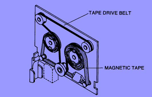
I've been following this thread with interest since I'm in the midst
of restoring an HP Dynamic Systems Analyzer with two of the same tape
drives installed. Both capstans were gooey. I considered the various
suggestions and came up with an easy, inexpensive and accurate way of
restoring the rubber coating on the capstan. Plasti Dip International
<http://plastidip.com/consumer/index.html> makes a coating for tools,
insulating, weatherproofing, etc. You dip the object you want to coat
as many times as necessary to build up the necessary layer. The
product has just about the right consistency to replace the old
capstan rubber and appears to have excellent wear characteristics.
I was able to add 0.021" [53.3] coating to the capstan in three dips
to bring the diameter to the proper value. The diameter varies less
than 0.001" [0.025] over several measures and the run-out is around
0.002" [0.051]. This was on the first try. The drive appeared to run
the tapes on hand properly.
A couple of hints:
- stir the stuff well. However, not so fast as to introduce bubbles.
- attach an extension to the can of dip and add one or two drops of
solvent to the top of the dip. This will ensure that the area above
the surface of the dip is saturated with solvent and will prevent
skimming.
- coat past the capstan onto the shaft. The added weight is
negligible and will ensure that the coating is uniform over the
capstan's surface.
My next try will be on a capstan for a DEC 7-track tape drive
belonging to a friend.
Pity.
And yes, I am sure Tony will be able to give us the tech details.
Unfortunately, e-Bay is not necessarily good news for those of us
outside the US. I investigated this route a while ago, and in most cases
shipping to South Africa will be prohibitively expensive.
>I am wondering whether it is possible to replace the ailing Sony 3.5"
>disc drives in both my HP9122D and HP9133H HP-IB units with PC 3.5"
>drives?
Not a chance! Tony Duell can give you all the technical
details but the
short version is that drives are completely different. The good
news is
that 9122 and compatible drives are frequently cheap on E-bay
and in
surplus stores.
Joe
I just thought I'd give an update on the various progress on the "new"
PDP-11 stuff that I'm working on.
As you all know the KM11 replica is now available. I have some
"accessories" made up for it (actually someone did them on their own and
I bought them). The accessories include some really cool plastic that
allows the overlays to be set up on the board. I'll put some more
information up on my website (http://www.shiresoft.com/products)
shortly. I still have to make up the actual overlays themselves.
I'm almost ready to send the MEM11A board out for fab. The layout has
passed all of the checks (both EagleCAD and the board house). So I
expect to have production boards ready by the end of April (protos back
by end of February, debug, etc). Production boards (to get "reasonable"
pricing) take 4 weeks. Just to let y'all know now, I'll need some firm
orders before I go and build the production boards. To get the price
I've indicated my website, I have to fork over ~$2K for the production
run.
I'm also finishing up a design for a "Unibus Analyzer". One of the
problems I've had in debugging Unibus systems has been to:
1. get all of the signals grouped reasonably so I don't have to
keep counting pins (and half the time getting it wrong) on the
backplane.
2. having reasonable triggers
3. being able to "see" all of the signals at once.
So, what I've done is design a board that goes in any SPC slot (...OK so
it's not strictly Unibus...shoot me):
1. buffers and groups all of the unibus signals for easy access for
a scope and/or logic analyzer probes (ie all address signals are
grouped together, all data, etc)
2. provides comparators for the address and data lines to provide
pattern matching to be used as a trigger for scope/logic
analyzer.
3. provides LEDs for *all* unibus signals.
Interested? Comments?
With the recent talk about providing a "cool" front panel for an 11/44,
I think I have an idea. I need to look at the details a bit more, but
here's what I think it'll be able to do:
1. set an address
2. examine contents of memory
3. write into memory
4. run/halt CPU (haven't quite thought that one out completely
yet).
5. switch register at a settable address.
It'll be a two board set, one goes into (you guessed it) an SPC slot and
has ribbon cables that go to the "lights & switches" that's mounted
where you want it. It should work in any Unibus 11, but obviously would
be best in 11/04, 11/24, 11/34, 11/44.
I also think that it could be adapted to be used in a Qbus system. I'm
taking the approach that the external lights & switches board would be
common between the Unibus and Qbus versions.
Do folks have other things they'd like done?
BTW the disk emulator project is progressing (but slowly...it's a
reasonably complex design and I want to get it "right"). These other
projects are actually helping me out with it.
--
TTFN - Guy
Anybody have any c64s or 128s kicking around?
I have some folks that are interested in SID chips, the computers need not be
working, I want 'em to scrap, and don't need the other parts to be good
either, nor the power supplies, cases, keyboards, etc. -- just the
boards.
I'm not looking to go beyond "yard sale prices", either.
--
Member of the toughest, meanest, deadliest, most unrelenting -- and
ablest -- form of life in this section of space, a critter that can
be killed but can't be tamed. --Robert A. Heinlein, "The Puppet Masters"
-
Information is more dangerous than cannon to a society ruled by lies. --James
M Dakin
It was pointed out to me today that the parts list that I supplied for
my KM11 replica has an error in it. For IC1-IC4 the part number has two
of the digits transposed. The correct part number is ULN2803A. The PDF
documentation and the parts list on the web site have both been updated
with the correct part number.
--
TTFN - Guy
I can't imagine any PC house not being able to use photo artwork to
produce the boards. The one thing a gerber file does provide is the
drill file with drill sizes, so you would need to take the padmaster and
identify the different hole sizes. The PC house will normally enlarge
the sizes you come up with so that the plating and solder reflow process
brings the holes sizes down to what you specify.
If indeed you have the master 2X or 4X layouts, an engineering photo lab
should be able to reduce them to 1X artwork.
BTW, I also have the photo artwork for several Polymorphic PC boards.
> Anyone know of any PCB firms that still do PCB production based on
> original Film art? I have most of the films for what was and wasn't
> produced by Atari, there are no digital files (heck some of these very
> early films, like the original Pong console are done with adhesive tape
> onto a clear plastic film for crying out loud!) So I am looking for a
> place that can still work with this old style way of making PCB's, anyone?
>
> Curt
>Date: Tue, 14 Feb 2006 03:55:02 +0000 (GMT)
>From: ard at p850ug1.demon.co.uk (Tony Duell)
>Subject: Re: eBay Item Not Won: Vintage Digital DECWriter IV terminal,
DEC,
>> Does anyone have DEC lineprinters or other printers w/out keyboards in
>> their collections? Pictures?
>I've got at least one LA100 (receive-only) in my collection (and I think
>a KSR one with a keyboard).
>Externally these look like a DECwriter 4, but have redesigned internals,
>with a printhead that's shiffted up and down mechancially to give twice
>the verical resouliton (the NLQ font is printed in 2 passes, one with the
>head in each posuition).
>-tony
---------------------------
Ah yes, that would be the Letterprinter 100 and the Letterwriter 100
respectively; I have a few of those myself awaiting a trip to the dumpster, as
well as some parts & ribbons. Tony, I naturally assume you have the
documentation set?
That reminds me of a little story: when we converted our clients from
Cromemco systems to PCs, we needed to convert the LA100s from
Xon/Xoff to hardware handshaking. After several days of asking techs at
DEC Canada and their reps and just getting unhelpful "can't be done" or
"yeah, I think there's a jumper somewhere (but no one knew where)" replies,
I finally called DEC US; when I asked the receptionist (those were the
days!) for the tech department, she asked me what it was about. Figuring
I was about to waste more time explaining the problem to someone who
wasn't going to be any help, I nearly fell off my chair when she replied,
"no problem, just run a jumper from pin 11 of IC27 to the pad beside pin
such-and-such of IC so-and-so (the actual details are buried in my notes
somewhere)". After I confessed and apologized for my sexist expectations
and told her that she was probably the only person in North America who
knew that, she laughed and admitted that a savvy engineer had happened
to be standing beside her and overheard what she'd repeated.
BTW, Tony, for someone as meticulous as you about some things, I'm
surprised to see so many typos in your messages lately; is this a hardware
or mushware problem, or none of my business?
mike
Does anyone on the list have an Atari ATW800 "Transputer Workstation"?
Just acquired one - am bringing it up, and have a few questions...
Dave
--
dave04a (at) Dave Dunfield
dunfield (dot) Firmware development services & tools: www.dunfield.com
com Collector of vintage computing equipment:
http://www.parse.com/~ddunfield/museum/index.html
I am wondering whether it is possible to replace the ailing Sony 3.5"
disc drives in both my HP9122D and HP9133H HP-IB units with PC 3.5"
drives?
These are the older Sony 3/4 height units with separate data & power
connectors, model OA-D32W-10 (double sided). The data connector has 26
pins. The power connector is standard 4 pin.
I located the pin-outs for these drives on a Japanese site, and found
that I could match all but 3 signals to a 'standard' 3.5" disc drive:
SONY OA-D32W-10 STANDARD
1 Motor On -----> 10 /MOTEA - 0=Motor Enable
Drive 0
2 Drive Select 0 -----> 14 /DRVSB - Drive Select 0
3 Disk Change -----> 34 /DSKCHG - 1=Disk Change/0=Ready
4 Drive Select 1 -----> 12 /DRVSB - Drive Select 1
5 Disk Change Reset -----> ????
6 Direction Select -----> 18 /DIR - 0=Direction Select
7 GND -----> GND
8 Step -----> 20 /Step - 0=Head Step
9 GND -----> GND
10 Write Data -----> 22 /WDATE - Write Data
11 GND -----> GND
12 Write Gate -----> 24 /WGATE - Floppy Write Enable,
0=Write Gate
13 GND -----> GND
14 Head Read -----> ????
15 GND -----> GND
16 Head Select -----> 32 /SIDE1 - 0=Head Select
17 GND -----> GND
18 Index -----> 8 /Index - 0=Index
19 GND -----> GND
20 Track 00 -----> 26 /TRK00 - 0=Track 00
21 GND -----> GND
22 Write Protected -----> 28 /WPT - 0=Write Protect
23 GND -----> GND
24 Read Data -----> 30 /RDATA - Read Data
25 GND -----> GND
26 Ready -----> ????
Is such a retro-fitting exercise possible? One possible problem could be
the rotational speed; I know the Sony drives spun at 600rpm as opposed
to the PC standard 300rpm... Any comments and/or suggestions about the
feasibility, as well as matching the signals of pins 5, 14, and 26?
Cheers
Glen.
I want one anyway. I WANT IT I WANT IT! Another
minimum mode 8088 I seem to perceive. Used to think
that amounted to an 8085, but its not limited to 64k.
Chuckie also chose a non-conformist Hitachi crt
controller. I ran across something else that used it
the other day, but I forget what it was.
--- cctech-bounces at classiccmp.org
<ard at p850ug1.demon.co.uk> wrote:
> >
> > what you get someone whos got everything else. Or
at
> > least every other IBM incompatible on the planet
(ok
> > Im not quite there). Also a must for the truly
> > masochistic (gcr floppies). What every guru/sicko
>
> The hardware is a bit odd... It clearly shows the
Chuck Peddle influence,
> it's full of 6522s (3 on the mainboard, 3 on the
disk controller), and
> the disk read/write circuit is very similar to that
in a Commodore PET
> drive...
>
> A couple of odd things. Firstly, the Centronics port
is driven by GPIB
> buffers (75160 and I think 75162). A 'little matter
of programming' and
> the right cable would get you a GPIB port there,
>
> Then there's the user port. A 50 pin header on the
mainboard. It's almost
> a complete 6522 (I think one of the port lines is
used to clock the sound
> circuitry), along with a light pen input and power
lines. Odd....
>
> And the sound iput. THe encoding half of the codec
is wired to the
> receive side of the 6852. The input to that codec
comes from a pin on
> header on the mainbosrd (along with power lines,
ground, etc). It would
> not be hard to feed an audio signal in there, the
hard part would be to
> write/find the necessary software....
>
> -tony
__________________________________________________
Do You Yahoo!?
Tired of spam? Yahoo! Mail has the best spam protection around
http://mail.yahoo.com
All:
I have an old Compaq 386 that I use for various tasks in the
shop. The Compaq BIOS has a fixed hard drive table and no "type 47 - user"
entry. So, I just used whatever I had for a drive in stock and I picked the
entry closest to the drive size.
This brings up an interesting query. I remember way back when, people sold
BIOS upgrade cards that provided a BIOS extension so that you could use hard
drives not originally designed for the computer. What were these boards
called?
Rich
Rich Cini
Collector of classic computers
Build Master for the Altair32 Emulation Project
Web site: <http://highgate.comm.sfu.ca/~rcini/classiccmp/>
http://highgate.comm.sfu.ca/~rcini/classiccmp/
/************************************************************/
The Museum of Computing is delighted to announce that Sir Clive Sinclair
will be guest of honour at the launch party for the Museums' latest
exhibition.
'CALCULATOR' from the Abacus to the Microchip opens to the public from 7th
March 2006 and will feature over 100 exhibits, tracing the history of the
incredible devices man has built to aid his mathematical manipulations.
The undoubted star of the show is the stunning gold plated Sinclair
Sovereign, once described as the worlds most beautiful calculator.
The exhibition will run for six months, admission is free.
For more information
www.museum-of-computing.org.uk
Simon Webb, Curator
Museum of Computing
My older brother was one of the developers of AOS/VS, the OS this machine ran. I have been looking for such a machine for a long time.
The MV's are early 32bit minis. They were competitive with the PDP's and other minis of the era (1980's).
They communicate with serial terminals mostly, and the terminal is slightly odd in its protocol (Dasher terminals). A DEC terminal will get you started, but will be frustrating.
There's a lot to know about these machines and there is at least one knowledgeable person on this list who has various DG equipment (other lines are the NOVA and ECLIPSE systems). They are one of the rarer minis.
And I apologize in advance for top-posting, and for the stupid little attachment that some users will see. I'm stuck on Outlook Web Access today and it doesn't play nice.
________________________________
From: cctalk-bounces at classiccmp.org on behalf of Glen Heiberg
Sent: Wed 2/15/2006 1:54 AM
To: cctalk at classiccmp.org
Subject: Data General MV/1400 info
Saw a Data General MV/1400 machine at a client site yesterday acting as
a coffee stand!
It's about the size of a 6U rack server standing on its side, mounted on
a 'foot'.
Apart from an ON/OFF button and the name badge, the front has a QIC-type
tape drive, and next to it a blanking plate that appears to be able to
house either another QIC drive or a floppy drive. Nothing else
interesting. Unfortunately I wasn't able to peek at the back.
Google didn't yield much on this machine. Anybody know more details?
Glen.
Unfortunately this not possible as the RPM of the drives is different.
Ironically, when I was looking for drives for my HP-85 I selected the
9122 because I thought I would have spares for the floppy drives. This
turned out not to be the case (plus I had to find the super rate EMS
ROM which meant that the 9122 sat on a shelf for about a year).
**vp
I lost yet another bid for the Technical Reference Manual for IBM PC-XT;
is there an online tech ref manual archive somewhere?
I hate to keep bugging you guys with questions; I'd rather consult tech
docs and *then* ask if I'm stumped. But if these things keep going for
$50, $100, or more on ebay I won't ever get a hold of a copy...
--
Jim Leonard (trixter at oldskool.org) http://www.oldskool.org/
Help our electronic games project: http://www.mobygames.com/
Or check out some trippy MindCandy at http://www.mindcandydvd.com/
A child borne of the home computer wars: http://trixter.wordpress.com/
There was once a website called "The Totally Unofficial ATW800 Page"
that was maintained by Chris Gray. Unforunately, it died like the
dinosaur years ago when the host provider decided accidently to end his
web account. I archived it locally on my website with the Chris'
permission (thank god for the wayback machine). It is basically
verbatim from the original site. You can find it here:
http://www.classiccmp.org/transputer/rtu_atw800.htmhttp://www.classiccmp.org/transputer/gs_atw800.htm
If you go the ATW800 specs, there are a lot of links to other users who
have the ATW800:
http://www.classiccmp.org/transputer/atw800.htm
These guys are more than happy to help fellow ATW800 users (especially
Jean-Marie). Also, there are much more documentation on ATW800 on the
previous link that is not contained in the Helios link...
I wish I could help you further, but I don't have one :-(
Cheers,
Ram
> -----Original Message-----
> From: cctalk-bounces at classiccmp.org
> [mailto:cctalk-bounces at classiccmp.org] On Behalf Of
> dave04a at dunfield.com
> Sent: Wednesday, February 15, 2006 10:52 AM
> To: General Discussion: On-Topic and Off-Topic Posts
> Subject: RE: Anyone with an ATW800 (Transputer workstation)?
>
>
> > Curt has one. The software is on my website at
> > http://www.classiccmp.org/transputer....
>
> Thanks (Already found your website :-)
>
> Actually, I received software with the unit, and it appears
> to have an installation already on the hard drive.
>
> I first powered the unit with the hard drive disconnected.
> This got me to the GEM desktop of the integrated Mega-ST.
> Booting the ATW800 Boot Disk resulted in an expected message
> that there is no SCSI drive.
>
> Connecting the SCSI drive, the unit did not appear to boot
> on it's own, however booting the ATW800 boot disk results
> in access to the hard drive, followed by startup message
> for the Helios server, and ends with the message
> "Booted..."
>
> After that, no more data comes from the Atari monitor
> connected to the Mega. However entering "trash" on
> the keyboard and pressing ENTER results in hard drive
> activity, so I assume the system is actually running,
> and outputting to the Blossum video display (?)
>
> I currently do not have an RGB monitor suitable for
> connection to the Blossum card - is there any way to
> direct the Helios console to the Atari Monitor.
>
> I have the Helios documents from your site (many thanks),
> but I have not found information specific to the ATW800,
> and how to get it up and running ...any pointers you can
> give me would be most helpful.
>
> Regards,
> Dave
>
> BTW: I have already posted IMD images of the disks that I
> received with it to my site. This includes the ATW800 boot
> disk, Helios dsiks, Something called "Mira shading", several
> disks marked "Xdemos", and several more marked "Public Domain".
>
> --
> dave04a (at) Dave Dunfield
> dunfield (dot) Firmware development services & tools:
www.dunfield.com
com Vintage computing equipment collector.
Curt has one. The software is on my website at
http://www.classiccmp.org/transputer....
Cheers,
Ram
> -----Original Message-----
> From: cctalk-bounces at classiccmp.org
> [mailto:cctalk-bounces at classiccmp.org] On Behalf Of Dave Dunfield
> Sent: Wednesday, February 15, 2006 8:36 AM
> To: cctalk at classiccmp.org
> Subject: Anyone with an ATW800 (Transputer workstation)?
>
>
> Does anyone on the list have an Atari ATW800 "Transputer Workstation"?
>
> Just acquired one - am bringing it up, and have a few questions...
>
> Dave
>
> --
> dave04a (at) Dave Dunfield
> dunfield (dot) Firmware development services & tools:
www.dunfield.com
com Collector of vintage computing equipment:
http://www.parse.com/~ddunfield/museum/index.html
At 10:13 AM 2/15/06 +0200, you wrote:
>I am wondering whether it is possible to replace the ailing Sony 3.5"
>disc drives in both my HP9122D and HP9133H HP-IB units with PC 3.5"
>drives?
Not a chance! Tony Duell can give you all the technical details but the
short version is that drives are completely different. The good news is
that 9122 and compatible drives are frequently cheap on E-bay and in
surplus stores.
Joe
>
>These are the older Sony 3/4 height units with separate data & power
>connectors, model OA-D32W-10 (double sided). The data connector has 26
>pins. The power connector is standard 4 pin.
>
>I located the pin-outs for these drives on a Japanese site, and found
>that I could match all but 3 signals to a 'standard' 3.5" disc drive:
>
>SONY OA-D32W-10 STANDARD
>
>1 Motor On -----> 10 /MOTEA - 0=Motor Enable
>Drive 0
>2 Drive Select 0 -----> 14 /DRVSB - Drive Select 0
>3 Disk Change -----> 34 /DSKCHG - 1=Disk Change/0=Ready
>4 Drive Select 1 -----> 12 /DRVSB - Drive Select 1
>
>5 Disk Change Reset -----> ????
>
>6 Direction Select -----> 18 /DIR - 0=Direction Select
>7 GND -----> GND
>8 Step -----> 20 /Step - 0=Head Step
>9 GND -----> GND
>10 Write Data -----> 22 /WDATE - Write Data
>11 GND -----> GND
>12 Write Gate -----> 24 /WGATE - Floppy Write Enable,
>0=Write Gate
>13 GND -----> GND
>
>14 Head Read -----> ????
>
>15 GND -----> GND
>16 Head Select -----> 32 /SIDE1 - 0=Head Select
>17 GND -----> GND
>18 Index -----> 8 /Index - 0=Index
>19 GND -----> GND
>20 Track 00 -----> 26 /TRK00 - 0=Track 00
>21 GND -----> GND
>22 Write Protected -----> 28 /WPT - 0=Write Protect
>23 GND -----> GND
>24 Read Data -----> 30 /RDATA - Read Data
>25 GND -----> GND
>
>26 Ready -----> ????
>
>Is such a retro-fitting exercise possible? One possible problem could be
>the rotational speed; I know the Sony drives spun at 600rpm as opposed
>to the PC standard 300rpm... Any comments and/or suggestions about the
>feasibility, as well as matching the signals of pins 5, 14, and 26?
>
>Cheers
>
>Glen.
>
I was cleaning out a cabinet to make some room and found several diskettes
for a Dynasty Smart Alec II system. Format is SSDD 5.25 48 tpi, but for
the first track which is SSSD--the system is CP/M-80.
I can find scant information on the web about this beast--I'm curious if
someone can fill me in.
Cheers,
Chuck
Saw a Data General MV/1400 machine at a client site yesterday acting as
a coffee stand!
It's about the size of a 6U rack server standing on its side, mounted on
a 'foot'.
Apart from an ON/OFF button and the name badge, the front has a QIC-type
tape drive, and next to it a blanking plate that appears to be able to
house either another QIC drive or a floppy drive. Nothing else
interesting. Unfortunately I wasn't able to peek at the back.
Google didn't yield much on this machine. Anybody know more details?
Glen.
Anyone still looking for one of these? I found one--I had it stashed away
with a bunch of PC CMOS clock chips.
Drop me a private email if so.
Cheers,
Chuck
on ebay. search it and check it out.
__________________________________________________
Do You Yahoo!?
Tired of spam? Yahoo! Mail has the best spam protection around
http://mail.yahoo.com
Hi
I've used a sharp chisel and hammer. No matter
how you do it, you'll break some plastic someplace.
I have good luck at keeping the main damage inside
the cover.
The most common failure is the transformer. It
will either be burnt up or have an open turn. If it
is open, it is usually the wire that runs across
the top of the coil and not inside the coil.
Of course, it is usually the primary that is open.
I find that the turns ratio is usually a nice integer
number. In other words, for 120V input, it might
have 120 or 240 turns on the primary. Things like that.
If the primary is badly burnt, you can use the secondary
as a input ( from another AC wall wart ) and a few turns
replacing the primary to determine the turns ratio.
Also, be warned that the cost of the wire is often
more than the value of the wart, unless you have a
good source. If you have several scrap warts of the
same size, you can often swap coils.
Dwight
>From: "Chuck Guzis" <cclist at sydex.com>
>
>Maybe it's the Scrooge in me, but I've got a couple of wall warts (power
>supplies) that either have open fuses or dried up caps in them. They're
>either multi-voltage or have unusual enough ratings (e.g. 18 vdc @ 1500 ma)
>that I'm reluctant to scrap them.
>
>Does anyone have a sure-fire method for getting into the case such that it
>can be reclosed? I was thinking about using a saw blade on a Dremel to
>separate the case halves.
>
>Cheers,
>Chuck
>
>
cctech at classiccmp.org,
I'm updating my address book. Please take a moment to update me
with your latest contact info.
Click the following link to correct or confirm your information: https://www.plaxo.com/edit_contact_info?r=4295311943-82525385--637936337
Name: cctech at classiccmp.org
Job Title:
Company:
Work E-mail: cctech at classiccmp.org
Work Phone:
Work Fax:
Work Address Line 1:
Work Address Line 2:
Work City, State, Zip:
Mobile Phone:
Home E-mail:
Home Phone:
Home Fax:
Home Address Line 1:
Home Address Line 2:
Home City, State, Zip:
Birthday:
P.S. I've included my Plaxo card below so that you have my current information. I've also attached a copy as a vCard.
+-----------------
| Jeff Silverman
| jeff at selectcomputer.net
| CEO
|
| Select Computer Technology Inc.
| 1605D Mabury Rd.
| San Jose, Ca 95133
| work: 408-944-9475
| fax: 408-944-9476
| mobile: 408-390-3760
| im: jsilve1260
| web: www.selectcomputer.net
+-------------------------------------
____________________________________________________________
This message was sent to you by jeff at selectcomputer.net
via Plaxo.
To opt out: https://www.plaxo.com/opt_out?r=4295311943-82525385--637936337
Plaxo's Privacy Policy: http://www.plaxo.com/support/privacy
Hi Henk
'Got the pointer wrong, should be:
http://www.elhvb.com/mboards/olivetti/systems1.html
Take care
Dwight
>From: "Gooijen, Henk" <henk.gooijen at oce.com>
>
>Thanks Dwight.
>I will do some more Googling tomorrow, and wade through the results :-(
>I tried the link a few times, but I get a 404. Will try it again tomorrow too.
>
>- Henk.
>
>________________________________
>
>Van: cctalk-bounces at classiccmp.org namens Dwight Elvey
>Verzonden: di 14-02-2006 21:19
>Aan: cctalk at classiccmp.org
>Onderwerp: Re: seeking connection information of CRT assy of Olivetti M21
>
>
>
>Hi Henk
> I just did some google and found a web page that
>looks like it may have technical docs for the M21.
>Look at:
>
>http://www.elhvb.com/mboards/olivetti/system1.html
<http://www.elhvb.com/mboards/olivetti/system1.html>
>
>Selecting cap1.pdf brings up a email request. I'm not
>sure if it will lead to anything but you might get a
>schematic showing the connector pins.
>Dwight
>
>
>>From: "Gooijen, Henk" <henk.gooijen at oce.com>
>>
>>Hi all,
>>I got an amber 10" monitor that was originally in an Olivetti M21.
>>I like the screen size and the color, so I would like to build some
>>sort of terminal with it. From the PCB comes a flat cable which
>>ends in a DB25 connector. As this is all connections I see,
>>I assume that it gets a low voltage power supplied via this cable.
>>
>>Does anybody have more info on this connector?
>>
>> thanks,
>>- Henk, PA8PDP.
>>
>>
>>
>>
>
>
>
>This message and attachment(s) are intended solely for the use of the addressee
and may contain information that is privileged, confidential or otherwise exempt
>from disclosure under applicable law.
>If you are not the intended recipient or agent thereof responsible for
delivering this message to the intended recipient, you are hereby notified that
any dissemination, distribution, or copying of this communication is strictly
prohibited.
>If you have received this communication in error, please notify the sender
immediately by telephone and with a "reply" message.
>Thank you for your cooperation.
>
>
produced a 68000 based high end graphical unit. The
only mention Ive ever heard was this dude in Australia
(who has one). Referred to it as a big loverly
toaster. Imagine being able to make fractals and cook
your English muffins with the same unit. Maybe hes on
the list and can discuss it further. I remember him
saying he managed to track down a tech who worked for
the company (wonder of wonders), but was only able to
provide the most basic info,
__________________________________________________
Do You Yahoo!?
Tired of spam? Yahoo! Mail has the best spam protection around
http://mail.yahoo.com
Thanks Dwight.
I will do some more Googling tomorrow, and wade through the results :-(
I tried the link a few times, but I get a 404. Will try it again tomorrow too.
- Henk.
________________________________
Van: cctalk-bounces at classiccmp.org namens Dwight Elvey
Verzonden: di 14-02-2006 21:19
Aan: cctalk at classiccmp.org
Onderwerp: Re: seeking connection information of CRT assy of Olivetti M21
Hi Henk
I just did some google and found a web page that
looks like it may have technical docs for the M21.
Look at:
http://www.elhvb.com/mboards/olivetti/system1.html <http://www.elhvb.com/mboards/olivetti/system1.html>
Selecting cap1.pdf brings up a email request. I'm not
sure if it will lead to anything but you might get a
schematic showing the connector pins.
Dwight
>From: "Gooijen, Henk" <henk.gooijen at oce.com>
>
>Hi all,
>I got an amber 10" monitor that was originally in an Olivetti M21.
>I like the screen size and the color, so I would like to build some
>sort of terminal with it. From the PCB comes a flat cable which
>ends in a DB25 connector. As this is all connections I see,
>I assume that it gets a low voltage power supplied via this cable.
>
>Does anybody have more info on this connector?
>
> thanks,
>- Henk, PA8PDP.
>
>
>
>
This message and attachment(s) are intended solely for the use of the addressee and may contain information that is privileged, confidential or otherwise exempt from disclosure under applicable law.
If you are not the intended recipient or agent thereof responsible for delivering this message to the intended recipient, you are hereby notified that any dissemination, distribution, or copying of this communication is strictly prohibited.
If you have received this communication in error, please notify the sender immediately by telephone and with a "reply" message.
Thank you for your cooperation.
I don't know if my first mail was send correctly.
Someone needs an sheet for osborne executive video
this should be the right one if the sold exceutive in germany ist
identical.-)
For the foghorn I must have to
search.
http://oldcomputers.dyndns.org/public/pub/rechner/osborne/executiv/manua
l/sheets/osbe_video.png
Mit freundlichen Gruessen
Fritz Chwolka
Hi Henk
I just did some google and found a web page that
looks like it may have technical docs for the M21.
Look at:
http://www.elhvb.com/mboards/olivetti/system1.html
Selecting cap1.pdf brings up a email request. I'm not
sure if it will lead to anything but you might get a
schematic showing the connector pins.
Dwight
>From: "Gooijen, Henk" <henk.gooijen at oce.com>
>
>Hi all,
>I got an amber 10" monitor that was originally in an Olivetti M21.
>I like the screen size and the color, so I would like to build some
>sort of terminal with it. From the PCB comes a flat cable which
>ends in a DB25 connector. As this is all connections I see,
>I assume that it gets a low voltage power supplied via this cable.
>
>Does anybody have more info on this connector?
>
> thanks,
>- Henk, PA8PDP.
>
>
>
>
>This message and attachment(s) are intended solely for the use of the addressee
and may contain information that is privileged, confidential or otherwise exempt
>from disclosure under applicable law.
>If you are not the intended recipient or agent thereof responsible for
delivering this message to the intended recipient, you are hereby notified that
any dissemination, distribution, or copying of this communication is strictly
prohibited.
>If you have received this communication in error, please notify the sender
immediately by telephone and with a "reply" message.
>Thank you for your cooperation.
>
>
"Jerome H. Fine" <jhfinedp3k at compsys.to> wrote:
>>Johnny Billquist wrote:
>
>
>>>> >"Jerome H. Fine" wrote:
>>>> > I have noticed what may be an interesting result when I use the
>>>> > PDP-11 Integer Divide Instruction "Div". Since I have noticed
>>>> > at least one individual who worked on the microcode for the
>>>> > PDP-11, perhaps there is an explicit "Yes / No" answer to my
>>>> > question:
>>
>>> Since this actually have nothing to do with the microcode, and
>>> actually is nothing specific with the PDP-11 DIV instruction, just
>>> about anyone should be able to answer definitely.
>
>
>Jerome Fine replies:
>
>I suggest that you might not be aware of the exact implementation
>of the PDP-11 integer "Div" instruction when an overflow occurs.
But the algorithm can't produce an overflow. However, it requires that
the math be unsigned. Herein lies a problem; the DIV instruction is
signed, so the result cannot be allowed to be > 32767. Afraid that
problem really kicks butt. Oh well, you cannot use the DIV instruction then.
Interestingly enough, it seems as if atleast E11 don't work the same way
as a real PDP-11 in this case. I really need to check this more. It
might be neccesary to report this to John Wilson.
In E11, the V flag is still set, but it also actually performs the
division. The J11 does not.
What have you tried your code on?
I believe it shouldn't have produced correct results for you on a real
PDP-11, but I believe it would on E11. Don't know about SIMH, or other
PDP-11 emulators (and I've only tested a real J11 so far, I'll try to
check on a real 11/70 tomorrow).
>Please see below!
Happy to.
>>>> > If I divide 196612 by 3 - i.e. "Div (R2),R0" where R0 = 3, R1 = 4,
>>
>>> (R2) = 3
>>
>>>> > the result (in addition to the condition bits) is R0 = 1, R1 = 1
>>
>>> which is
>>
>>>> > exactly correct if the quotient is regarded as a 32 bit result with
>>
>>> R0 being
>>
>>>> > the low order 16 bits of that result and the high order 32 bits are
>>
>>> somewhere
>>
>>>> > else - probably inaccessible as far as programming is concerned,
but
>>
>>> easily
>>
>>>> > obtained by:
[...]
Well, now that I'v actually tested this, I can tell you that this works
in E11, but does not work on a J11. If you load R0=3, R1=4, R2=3 and do
a DIV R2,R0, the only thing that happens is that the V-bit of the PSW is
set, and the registers remain unchanged.
>I agree that the above code is the "correct" method to ensure
>a valid result. BUT, that is NOT what I am attempting to determine.
Well, what we now know is that the piece of code you have will not
actually produce correct results on a real PDP-11, since we have a
overflow into the sign bit, which aborts the DIV instruction.
>Specifically, I have found that the following code also works:
> Mov R0,R3
> Div (R2),R0 ; First Divide Instruction
> Tst R1
> Bne Somewhere - since the quotient is not of interest when a
non-zero remainder
> Mov R0,-(SP)
> Mov R3,R1
> Clr R0
> Div (R2),R0 ; Second Divide Instruction
> Mov (SP)+,R1
>At this point, R0 / R1 now contains 32 bit quotient IF the first
>"Div" instruction places the low order 16 bits of the 32 bit
>quotient into R0. I have found this result in practice and since
>there is a VERY HIGH probability that the remainder is NOT
>zero, the above code is MUCH faster.
And this will totally fail on atleast a J11, and probably all other
"real" PDP-11s. At overflow, nothing gets computed. The register remain
unchanged.
>Again, the specific question is IF the quotient of the "Div" instruction
>is the low order 16 bits of a 32 bit quotient all of the time or just
>when the high order 16 bits are all zero????????
Basically never. It the quotient can't be expressed in *15* bits, the
registers will remain unchanged.
>>>> > Can anyone confirm what I have found in practice?
>>
>>> Certainly. It's basic math, the way it's taught in elementary school.
>>> That was atleast the first way I was taught how do do divides on big
>>> numbers on paper.
>
>
>I learned that also, but the observation is not relevant
>to my question.
True. The algorithm is correct, but the PDP-11 DIV instruction have more
limitations. You could use it if you played with smaller quantities.
Easiest would be to work at 8 bits at a time instead of 16. However,
that also requires the divisor to only be 8 bits, which might be a bit
limiting. If you do 15 bits at a time, you're at the limit of the DIV
instuction, but still working. You have to do the bit packing and
unpacking though.
And all that will probably take much more time than just implementing a
DIV yourself.
>I realize that the DEC manual description of the "Div" instruction
>does not address the situation when the quotient exceeds 65535
>(decimal) or 16 bits, but again, perhaps someone who knows
>the microcode might have an answer.
Uh. My processor handbooks actually do address the situation, but it's
actually when it exceeds 32767.
And I have three different processor handbooks here.
(1977-1978 pdp11/70 processor handbook, 1979-1980 pdp11 processor
handbook for pdp11/04/34a/44/60/70, and 1983-1984 PDP-11 Architecture
Handbook).
Look in any processor handbook you have at the DIV instruction, and the
V condition.
>>>> > Even better would be a method of retrieving the high
>>>> > order 16 bits of the quotient in a manner which takes
>>>> > fewer instructions and without a second divide instruction!
>>
>>>
>>> I doubt you'll find it.
>
>
>I AGREE!! It would have been "nice" though if
>DEC knew where the value was and made that high
>order 16 bits available via the next instruction
>if the user needed it. That information would
>also have exactly defined whether or not the low
>order 16 bits of the quotient and the remainder
>were correct all of the time. Any comments on these
>TWO observations?
Unfortunately, the DIV instruction is explicitly a 16-bit signed divide.
They actually don't do a 32-bit divide, so there aren't any upper 16
bits to tell about somehow.
>I realize that the instruction set is long past being
>subject to change in DEC hardware, but that does not
>mean that an emulator could not manage to make a few
>small but vital improvements. And certainly, at least
>in SIMH, it is possible to examine the code to determine
>the answer to my original question. Does anyone have
>the code for the "Div" emulation in SIMH and what does
>happen when the high order 16 bits of the quotient are
>non-zero?
Afraid I haven't looked at simh in a while, and I also apologize for my
previous answer. I was just observing the algorithm, and not how the
PDP-11 DIV instruction actually worked.
I should have looked in the processor handbook, which I did this time.
But then again, since you observed that your code worked, then I had no
reason to doubt it.
But in fact, it will not work on a real PDP-11.
Johnny
--
Johnny Billquist || "I'm on a bus
|| on a psychedelic trip
email: bqt at update.uu.se || Reading murder books
pdp is alive! || tryin' to stay hip" - B. Idol
Hi all,
I got an amber 10" monitor that was originally in an Olivetti M21.
I like the screen size and the color, so I would like to build some
sort of terminal with it. From the PCB comes a flat cable which
ends in a DB25 connector. As this is all connections I see,
I assume that it gets a low voltage power supplied via this cable.
Does anybody have more info on this connector?
thanks,
- Henk, PA8PDP.
This message and attachment(s) are intended solely for the use of the addressee and may contain information that is privileged, confidential or otherwise exempt from disclosure under applicable law.
If you are not the intended recipient or agent thereof responsible for delivering this message to the intended recipient, you are hereby notified that any dissemination, distribution, or copying of this communication is strictly prohibited.
If you have received this communication in error, please notify the sender immediately by telephone and with a "reply" message.
Thank you for your cooperation.
Hi guys !
Should anyone help me and give me some informations regarding the
keyboard signals and keyboard's connector pin assignment from the IBM
5151 terminal ?
I supposed the pin assignment was the same as for the IBM 5121but it's
not true...
(The keyboard connector of the 5151 is a DB25 female, and using a single
gender changer is not enough).
Many thanks for your help !
Fred.
--... ...-- -.. . ..-. ..... .. -. .-..
73 de F5INL
On Sun, 2006-02-05 at 14:15 -0800, vrs wrote:
> From: "Brad Parker"
> > Turns out the RX02 emulator needs an M105 and M7821 single height UNIBUS
> > card to work.
> >
> > Anyone have an extra M105 and M7821?
I have a number of M105 and M7821 boards available. $15/ea (ie $30 for
the pair) + shipping. If anyone's interested.
--
TTFN - Guy
> I have one of these at home and am also looking for disk images -
> especially the terminal emulator program.
they'll be up for a day or two at http://www.bitsavers.org/HP4952A as
a dmk and raw images
That would certainly be a good approach, but also definitely not the easiest.
Writing the required code in "pseudo language", then code in 8085 assembler
and burn in EPROM is just one step, but you need some 50-60 I/O lines to
control the lights and read the switches. That's additional hardware ... but
I have not [yet] looked at the diagram of the 11/70 console. Perhaps you can
modify it slightly and add multiplexers to get the I/O line count down.
Also, but this depends a bit on the console you want to hang on the /44, you
cannot simply connect the (data) LEDs to that UNIBUS DATA lines, because
depending the knobs (on a /45 or /70) you must display something different.
OTOH, a good question would be "to what extend must the attached panel be
operational? Fully or partially?"
If you select the /35 (aka /40) or even easier the /20 or /10 console you can
safe yourself a lot of work. Or go one step further and add the /34 or /60
console on the /44. Not *that*, I would certainly *not* start on.
Indeed, not going to attempt any of this, not even in the far future!
But I would love to read the workz of others in this area!
- Henk.
________________________________
Van: cctalk-bounces at classiccmp.org namens Tony Duell
Verzonden: ma 13-02-2006 16:52
Aan: cctalk at classiccmp.org
Onderwerp: Re: sexy PDP-11/44 panel (was: Re: Original 11/74 front panel)
>
> Without thinking much about it, I'd say that mounting any
> real blinkenlight console on a 11/44 is *not* trivial!
> Of course, grabbing UNIBUS address- and data-lines and wiring
> that to the lights is trivial, but to get all panel functions
> (LOAD ADDR, DEP, EXAM, etc). working on an 11/44 is more work.
I wondered about wiring the panel to the 8085 console processor, and
re-writing that firmware to take commands from the panel switches, not
>from the serial port.
But it's not something I am likely to work on any time soon...
-tony
This message and attachment(s) are intended solely for the use of the addressee and may contain information that is privileged, confidential or otherwise exempt from disclosure under applicable law.
If you are not the intended recipient or agent thereof responsible for delivering this message to the intended recipient, you are hereby notified that any dissemination, distribution, or copying of this communication is strictly prohibited.
If you have received this communication in error, please notify the sender immediately by telephone and with a "reply" message.
Thank you for your cooperation.
I have created new disks. I was interpreting the DS/SS index hole
incorrectly on the first try. Still trying to create ImageDisk images also.
Doing these next, probably by Wednesday.
Kelly
Very true, Pierre.
It is a matter willingness to travel several hundreds of kilometers just
to get something, but in the first instance it's of course a matter of luck.
The years that the real old stuff was thrown out are gone. An 11/34 can be
found with some patience, but the machines with many lights and switches
are indeed becoming a "rare find".
Edward and I travelled from The Netherlands to Italy to get two (!) 11/70's
... already some four years ago! We did not pay $1000 for the machines, but
we both paid $400 for the truck rental. Almost the same, as in the end,
your wallet is just as empty :-(
- Henk.
________________________________
Van: cctalk-bounces at classiccmp.org namens Pierre Gebhardt
Verzonden: ma 13-02-2006 18:26
Aan: General Discussion: On-Topic and Off-Topic Posts
Onderwerp: Re: sexy PDP-11/44 panel (was: Re: Original 11/74 front panel)
> I guess there are more people on the list who have a boring
> PDP-11/44 with a dull panel, that would like to make the /44
> more sexy with an 'appropriate' panel. The "upgrade" is,
> of course, done in such a way that it can be undone ...
> I (we) do not have a /74 panel :-(
Well Henk, at least, you HAVE PDPs with a "lights and switches" console.
Please think of those (I'm part of them!) who are eager to get one. 11/24 or
11/73s are nice, but unfortunately not the same. Today, it's almost impossible
to get one...if you don't consider the possibility of buying one for a 1000$.
THAT'S definitely the case for students like me.
... 11/74s are really cool! Thanks for that nice picture, Tim.
Regards,
Pierre
This message and attachment(s) are intended solely for the use of the addressee and may contain information that is privileged, confidential or otherwise exempt from disclosure under applicable law.
If you are not the intended recipient or agent thereof responsible for delivering this message to the intended recipient, you are hereby notified that any dissemination, distribution, or copying of this communication is strictly prohibited.
If you have received this communication in error, please notify the sender immediately by telephone and with a "reply" message.
Thank you for your cooperation.
8765626540 Cromemco System Three Case Kinda Rough Pickup Only
8765634509 Ohio Scientific OSI C3 Cabinet Incomplete Pickup Only
8765637723 IBM System/23 Datamaster for Pickup Only
8765639131 IBM 5247 Hard Disk Unit for Pickup Only
If anyone goes out there and isn't interested in the Cromemco/OSI
stuff, I'd like to talk to them :-).
--
"The Direct3D Graphics Pipeline"-- code samples, sample chapter, FAQ:
<http://www.xmission.com/~legalize/book/>
Pilgrimage: Utah's annual demoparty
<http://pilgrimage.scene.org>
The VT103 had a Q-bus backplane. The VT105 and VT125, and several
compatible, were all add ons. The VT101, 02, 31, and 32 were just different boards in
the same unit. There was also the PDT11/130, and a few others.
Paul
> I guess there are more people on the list who have a boring
> PDP-11/44 with a dull panel, that would like to make the /44
> more sexy with an 'appropriate' panel. The "upgrade" is,
> of course, done in such a way that it can be undone ...
> I (we) do not have a /74 panel :-(
Well Henk, at least, you HAVE PDPs with a "lights and switches" console.
Please think of those (I'm part of them!) who are eager to get one. 11/24 or 11/73s
are nice, but unfortunately not the same. Today, it's almost impossible to get one...if you
don't consider the possibility of buying one for a 1000$. THAT'S definitely the case for
students like me.
... 11/74s are really cool! Thanks for that nice picture, Tim.
Regards,
Pierre
______________________________________________________________
Verschicken Sie romantische, coole und witzige Bilder per SMS!
Jetzt bei WEB.DE FreeMail: http://f.web.de/?mc=021193
although its been refuted on this list, I do seem to
recall reading that plugging a 5151 into a CGA card
was catastrophic - read IMPLOSION. Alas only a
suburban legend. And as much as Id like to see it (not
that I have anything against 5151s), Im not going to
be trying it anytime soon. No way, no how...
--- cctech-bounces at classiccmp.org <cclist at sydex.com>
wrote:
> On 2/2/2006 at 5:29 PM Richard wrote:
>
> >Yes, its referred to as the "Killer Poke". There
was also something
> >you could do on early IBM PC graphics adapaters
where you could fry
> >the monitor by writing a zero value to a frequency
register, IIRC.
>
> All you really had to do to fry the MDA on a PC was
to program the
> horizontal frequency a few KHz too high. The
display would keep sync, but
> eventually the HOT would get smoked. I fried a
couple of HOTs while
> working on SIMGA--fortunately, the distributor for
the monitors was about 6
> blocks away and they had an ample supply of
replacement parts.
>
> But heck, that isn't dramatic. The display just
goes dark.
>
> I want a Star Trek-type "ERROR ER ROR MUST RE
EVALUATE" type of smoke and
> sparks type of software failure ending in an
explosion of thermonuclear
> proportions...
>
> Cheers,
> Chuck
>
>
__________________________________________________
Do You Yahoo!?
Tired of spam? Yahoo! Mail has the best spam protection around
http://mail.yahoo.com
If anybody has them to spare, I could use *one* STD bus connector (okay, and
maybe a spare :-) for the spot on my BigBoard 2 that allows for that...
I also have a partially-constructed S-100 backplane, made by Vector (I'm
still missing a few Tantalum caps for the active termination portion) but
need the S-100 connectors to go into it. Not something I can afford to
invest in at this point in time, funds being rather tight, but if you have
some of these connectors that you'd be willing to part with...
--
Member of the toughest, meanest, deadliest, most unrelenting -- and
ablest -- form of life in this section of space, a critter that can
be killed but can't be tamed. --Robert A. Heinlein, "The Puppet Masters"
-
Information is more dangerous than cannon to a society ruled by lies. --James
M Dakin
Roy J. Tellason <rtellason at blazenet.net> wrote:
> But no drill press or serious holding hardware to do that in.
Surely you can improvise, just screw the metal bracket to a piece of
flat wooden surface (e.g. leftovers from IKEA bookcases). I also find
that its easier if you start with a very thin bit to drill a guide hole.
> One further complication is that the ones for floppies were designed to hold
> the drive right flush up against the front panel, while the ones for HDs
> held it much further back, giving better airflow. If I *did* drill holes
> for the purpose the HD would be much too far forward, depending on which
> case I was sticking it in.
Ah, yes, in that case you may want to copy a scheme that was used on
Olivetti servers. These had 10-15 5mm holes on the plastic panel sitting
in front of the drive (the thing you remove if you want to mount a tape
drive or CDROM). These provided more than adequate ventilation for the
drives which were placed just behind the panel. I have used the same trick
on a machine that had a bunch of Seagate 75Gb SCSI drives (these were
getting real hot) and it allowed sufficient cooling to let them operate
24/7 in an office environment.
**vp
Anybody familiar with these boxes? We've acquired one at Bletchley (a
9000/800/v2200) but no documentation, so getting an OS installed on it is
proving to be a nightmare - hence finding someone who has details and would be
willing to look up a few odds and ends would be most handy!
HP's website seems spectacularly useless in documenting the hardware /
resident firmware and only covers the OS side of things :(
cheers
Jules
Hi All,
I have noticed what may be an interesting result when I use the
PDP-11 Integer Divide Instruction "Div". Since I have noticed
at least one individual who worked on the microcode for the
PDP-11, perhaps there is an explicit "Yes / No" answer to my
question:
If I divide 196612 by 3 - i.e. "Div (R2),R0" where R0 = 3, R1 = 4, (R2) = 3
the result (in addition to the condition bits) is R0 = 1, R1 = 1 which is
exactly correct if the quotient is regarded as a 32 bit result with R0 being
the low order 16 bits of that result and the high order 32 bits are
somewhere
else - probably inaccessible as far as programming is concerned, but easily
obtained by:
Mov R1-(SP) ; Save low order 16 bits of dividend
Mov R0,R1 ; Divide high order 16 bits
Clr R0 ; of dividend
Div (R2),R0 ; by the divisor
Mov R0,R3 ; Save high order 16 bits of quotient
Mov R1,R0 ; Divide the remainder
Mov (SP)+,R1 ; of the dividend
Div (R2),R0 ; by the divisor
i.e. R3 now contains the high order 16 bits of the 32 bit quotient
with R0 holding the low order 16 bits of the 32 bit quotient
Reason for the question: I require the complete quotient
ONLY when the remainder is ZERO (specifically when the
dividend is not a prime number since (R2) is ALWAYS a
prime number). Thus, if I can avoid performing the first
division except when the remainder is zero and I require
the high order 16 bits of the quotient to continue, I can
optimize the code. Thus far I have tested the code on
numbers up to 100,000,000 when I divide by 3 and the
results are always correct.
Can anyone confirm what I have found in practice?
Even better would be a method of retrieving the high
order 16 bits of the quotient in a manner which takes
fewer instructions and without a second divide instruction!
For those who are interested, I am attempting to calculate
the Mobius Function - mu(n). If you check on Google, mu(n)
requires the number of factors of n. Thus while a sieve
program can be used to remove the prime numbers, the
rest of the numbers must be factored to obtain the number of
factors.
Sincerely yours,
Jerome Fine
--
If you attempted to send a reply and the original e-mail
address has been discontinued due a high volume of junk
e-mail, then the semi-permanent e-mail address can be
obtained by replacing the four characters preceding the
'at' with the four digits of the current year.
I think the ANSF-Q7 (SAGE) was seen on Voyage To the Bottom of the Sea. I've
also seen it on several other movies and TV shows, but don't recall which ones.
Paul
What cards exist that you can plug into the VT-100 backplane?
Has anyone any experience with making your own card to plug into it
for a graphcis overlay feature?
--
"The Direct3D Graphics Pipeline"-- code samples, sample chapter, FAQ:
<http://www.xmission.com/~legalize/book/>
Pilgrimage: Utah's annual demoparty
<http://pilgrimage.scene.org>
http://marketplace.vintage.org/view.cfm?ad=2080
Someone needs to save this. In the ideal world, it should
go to the CHM, though I don't know if they have one of the
DAP series, or even if they care (it appears all they want
are boxes with lights to go "ohhhh ahhhh" at).
There were not many sold (like 5...), and it says it has the software.
Normally, they would be attached processors to something
like a Sun.
Dick Lyon had a small one in Apple ATG in the late 80's..
http://www.new-npac.org/projects/cdroms/cewes-1999-06-vol1/nhse/
hpccsurvey/orgs/cpp/cpp.html
This may be the same machine offered back in 2003 on the list.
Episode 28 - "The Alternate Side"
When Jerry is trying to pick up his rental car, the
agents are using TRS-80 model III computers, I
believe.
http://black-celebration.net/caps/displayimage.php?album=21&pos=43
__________________________________________________
Do You Yahoo!?
Tired of spam? Yahoo! Mail has the best spam protection around
http://mail.yahoo.com
in particular the version - Infoshare ( = OEM Netware
1.0?) - that ran on the Televideo Personal Mini PM/16T
(80186 based).
__________________________________________________
Do You Yahoo!?
Tired of spam? Yahoo! Mail has the best spam protection around
http://mail.yahoo.com
I need the install media (disk or tape) for ViewPoint version 1.0 for the
Xerox 6085. Does anyone have this? If so, please contact me directly.
<sellam at vintagetech.com>
Thanks!
--
Sellam Ismail Vintage Computer Festival
------------------------------------------------------------------------------
International Man of Intrigue and Danger http://www.vintage.org
[ Old computing resources for business || Buy/Sell/Trade Vintage Computers ]
[ and academia at www.VintageTech.com || at http://marketplace.vintage.org ]
I've been using a Linux box as a firewall for the cable modem before
Linksys and the other networking companies came out with small router
boxes. Along the years the uses for the box have grown, so I do a
little hacking on it, some file servering, backup/restore to the Windoze
boxes, etc.
The original box was an old 486-66 running Redhat 6.1. (It ran OS/2 2.1
originally). I only decommissioned it last year, and it is still
sitting in the room waiting for it's next purpose in life.
The current box is a Pentium 233, and it's been doing just fine except I
fear that it's starting to crap out. It will not boot off of a floppy
disk no matter what I try. I've tried 2 cables, 3 drives, and four
different known good boot disks. I've stripped the system down, screwed
with the onboard setup, etc. To make a long story short, after 3 hours
I've finally decided that the onboard FDC controller is heading south.
Disks are still readable, but only after you've booted from hard disk.
The motherboard was an ABIT IT5H - good at the time, but given ABIT's
reputation at the time I'm really happy that it made it this far.
Since the end is near for this machine, it's time to get my data off of
it and find a replacement. I'm thinking of something:
- a little more robust .. ie, quality
- needs to take a few PCI cards. Right now I use 2 NICs, 1 SCSI, and 1
video card. If some of those functions are on the motherboard that is fine.
- Can be left on continuously and ignored.
What's a good source for stuff like this? I'm thinking of monitoring
eBay for items I can do local pickup on, but I'm not sure if small
businesses that have this kind of hardware take the time to put it out
on eBay when it comes time to upgrade. (I'm in Rochester MN, so my
sources of this stuff are limited.)
Any ideas on the floppy controller?
Yikes, this was even crazier, although I suppose the rarity was what
caused it.
Closed at $354.
That's more than I paid for the PDP-11/03, dual RL01s, 23 RL01 packs,
full set of manuals, LA-120 and VT-100, including gasoline for the drive
out and back (1100 miles).
I couldn't dig up anything on the net about this terminal. Has anyone
on the list seen one? (or were you the person who bought it on ebay?
:-) ... you can tell me privately and I'll keep the secret!)
--
"The Direct3D Graphics Pipeline"-- code samples, sample chapter, FAQ:
<http://www.xmission.com/~legalize/book/>
Pilgrimage: Utah's annual demoparty
<http://pilgrimage.scene.org>
Eric F. (elf at ucsd.edu) asked:
"Anyone who has seen it know what computer it was?"
A quick check of Google have multiple (independant?) web sites saying:
"an IBM 7090 with a 1401 front-end" and "the 1403 printer playing a
pivotal role in the plot"
Although I've seen the movie multiple times, I'm a DEC guy and can't
identify IBM equipment. (as opposed to the PDP-8 in "Three Days of
the Condor"))
Thomas
> -----Original Message-----
> From: Chuck Guzis [mailto:cclist at sydex.com]
> Sent: Saturday, February 11, 2006 11:53 PM
> To: cctalk at classiccmp.org
> Subject: RE: Tandy Xenix disk images
>
>
> On 2/11/2006 at 5:46 PM Kelly Leavitt wrote:
>
> >> If anyone needs them, download them and give them a try. Let
> >> me know which
> >> works. The second image of the second disk is a single sided
> >> image, which
> >> should be all you really need.
>
> Kelly, how can I tell if I've got the right flavor Model 16
> to run this
> thing?
>
> Thanks,
> Chuck
>
>
Chuck:
The 16 will need to have the last PAL upgrade, with checksum 3646D4 on U36.
This would be on the 68000 CPU board. I have version 3.0 around somewhere
that doesn't require that upgrade. I'll image that when time permits.
Kelly