
23 Dec
2016
23 Dec
'16
6:48 p.m.
On 2016-Dec-23, at 4:52 PM, Adrian Graham wrote:
Thanks for all the help so far, I've moved on quite a way but I still
haven't managed to get my head around op-amps other than the basics. If I
may trouble your experienced heads with a small circuit diagram:
http://www.binarydinosaurs.co.uk/STCExecutelStartupCircuit.jpg
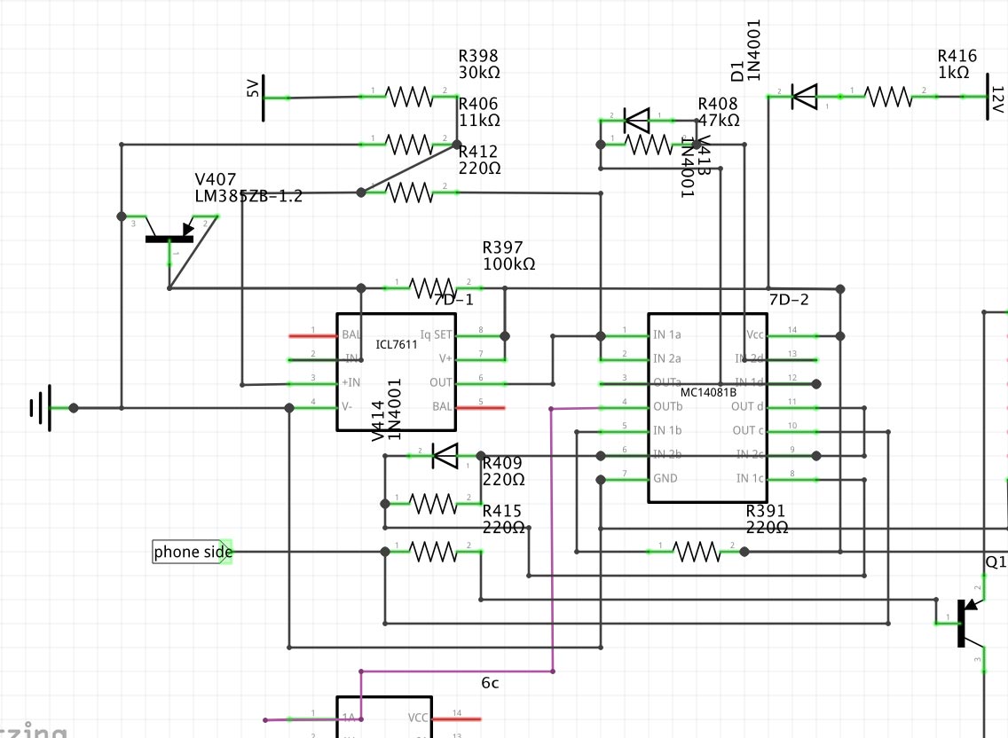
This is the full circuit of all the things I've been posting recently,
traced and drawn out as completely as I can manage. All the resistors and
diodes have been tested out of circuit and are OK and I've just realised 3
of the resistors are labelled wrongly. R409 is 47k, R415 and R391 are 100k.
IN- at the op-amp is 1.2V from the LM385ZB-1.2 which has pins 2/3 tied
together. IN+ is 1.3V. V+ is 5.3V. The purple trace is RESET for the 8085,
or should be.
Initially the LM385Z had rotted away because of battery leakage so I was
experimenting with diodes in series to try and get the IN- voltage down to
1.2V, and with two IN4148s (0.9V) the whole circuit sprang into life and I
got RESET at the 8085. For two seconds, then it would cycle for two seconds.
This maybe expected behaviour, I don't know.
3 diodes gave me 1.3V which produced nothing at the op-amp output, probably
because there was no difference between IN+ and IN-?
On a whim I managed to solder new legs onto the old LM385Z and it works,
giving 1.2V at IN-, but the output is still only 0.2V.
I don't mind admitting I'm stumped :)
The op amp is configured as a schmitt trigger or comparator with hysteresis:
There is no negative feedback so it is operating at full gain and functions like a
comparator.
However there is positive feedback via R412 (*1), this adds hysteresis to the trip
point(s).
(Brief hackneyed, not rigorous, theory of op: As the input differential varies
past the trip point, the output pulls the + input
further above or below the point at which it just tripped, so the inputs now have
to 'overcome' a greater differential
to trip as the input differential varies in the opposite direction.)
One input to the (now) comparator is the 1.2V from V407 regulated down from some power
rail.
The other input is the ~ 1/4 voltage divider down from +5V formed by R398 & R406
(netting 1.34V @ 5V).
It appears the idea is that as the +5 supply ramps up at power-on the comparator trip (and
hence release of reset) is delayed till the +5 reaches something around +4.5V.
The ICL7611 is, I expect, a very-low-power (Intersil's niche) op amp. Together with
the CMOS 4081 the circuit appears tailored for low-power operation.
Is it supplied by the battery?
It may require the battery presence for stable supply at time of power-up to get reliable
reset operation from this power-on-reset circuit.
The diode-resistor pairs at the 4081 AND gate inputs turn the AND gates into
'asymmetric edge delay gates': the resistor together with some capacitance delays
the switching of the gate for an edge of one direction, while the diode shorts the delay
for an edge of the other direction.
If there is no cap at the input, they must be relying on the gate capacitance of the CMOS
inputs, making for a pretty short delay.
*1: Are you sure that's a 220? resistor? It's awfully small compared to the
impedance of the voltage divider feeding it.