


"Voltmitten": an amateur overdesigns a DC voltage monitor
by stepleton@gmail.com
4 years, 5 months
- 1
- 0


What is this massive binder of computer minutes1955 to 1964. I did cel phone or of text below we have
by couryhouse@aol.com
4 years, 6 months
- 1
- 1


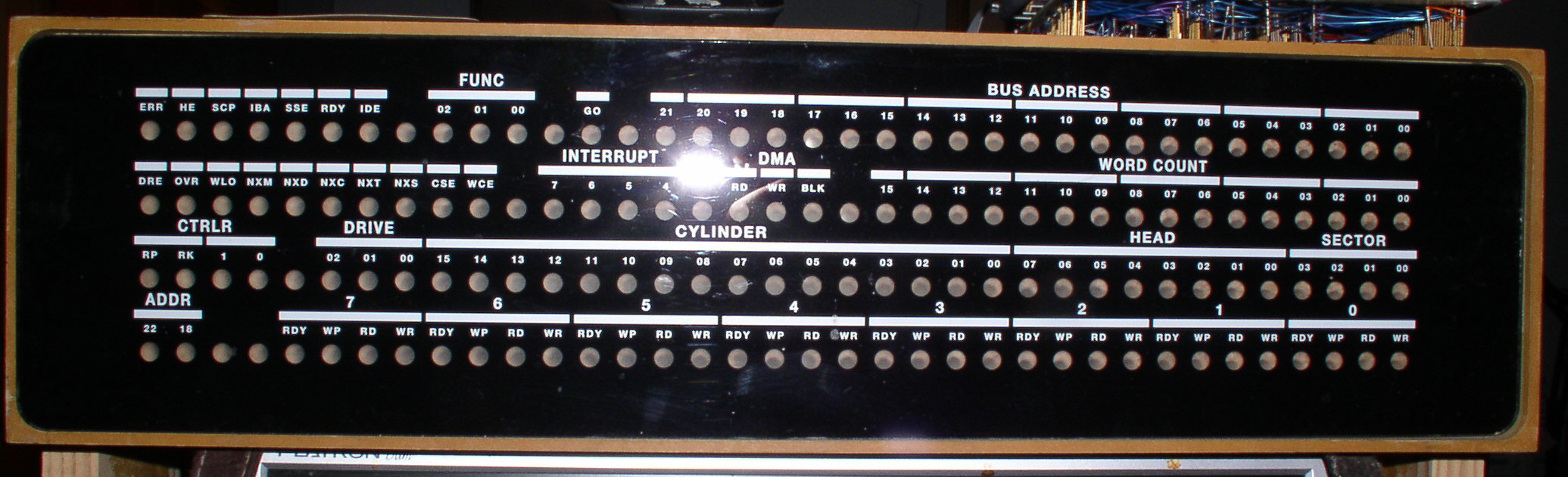
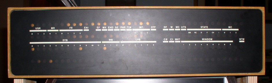
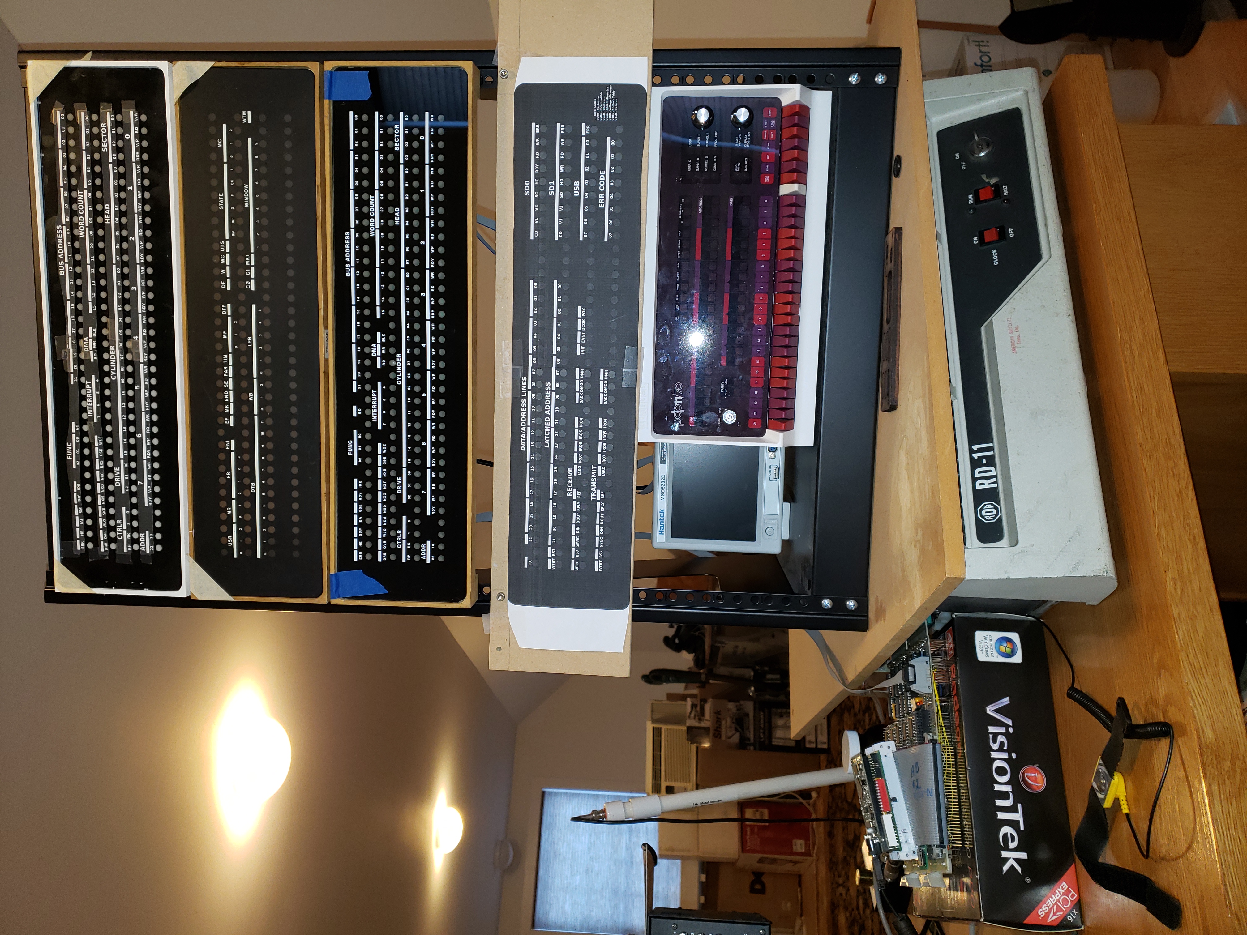
RC11 controller (Was: Reproduction DEC 144-lamp indicator panels)
by jnc@mercury.lcs.mit.edu
4 years, 6 months
- 4
- 6


Need picture of power supply mounted in 11/40 cabinet
by jnc@mercury.lcs.mit.edu
4 years, 6 months
- 1
- 0


Hand tool to remove a difficult (stuck) circuit board
by wh.sudbrink@verizon.net
4 years, 6 months
- 1
- 0


Reproduction DEC 144-lamp indicator panels (was Re: RK11-C indicator panel inlays?)
by ethan.dicks@gmail.com
4 years, 6 months
- 1
- 0