


Lecture: Forth: from the minicomputer to the microcontroller, 2021-05-08, 19:00
by stueberahoo@yahoo.de
5 years, 1 month
- 1
- 0


IBM 1410 FPGA Implementation Update - new github repository
by michael.99.thompson@gmail.com
5 years, 1 month
- 2
- 1


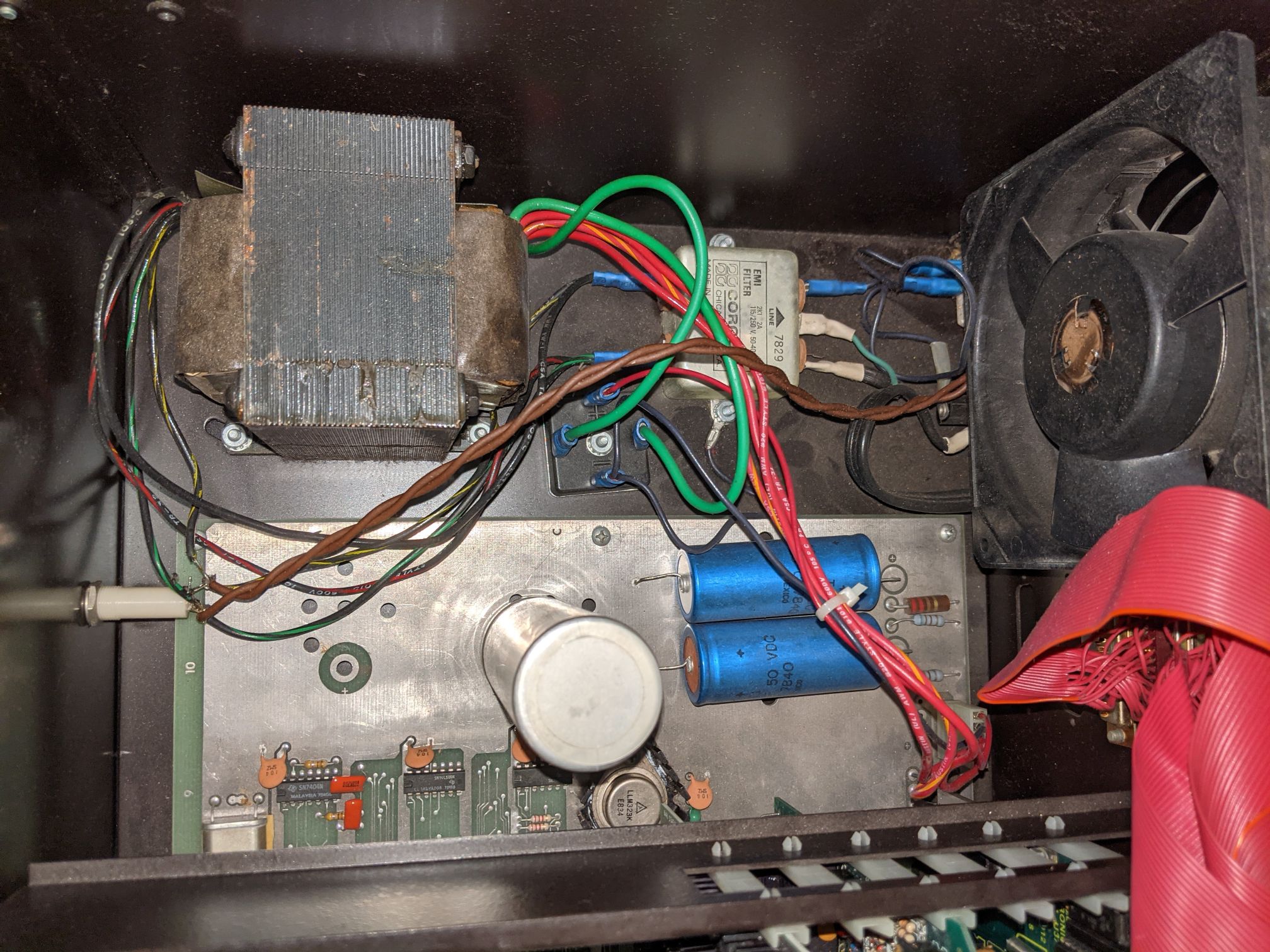
Sprague 2X.1-1000 filter capacitors and 854-B power control assembly
by ccth6600@gmail.com
5 years, 1 month
- 2
- 2

IBM 1410 FPGA Implementation Update - new github repository
by cube1@charter.net
5 years, 1 month
- 4
- 6

Looking for the person I sold an eMachines eOne to at the VCF Swap Meet on April 24
by tony.aiuto@gmail.com
5 years, 1 month
- 2
- 1


FTAG: AlphaServer DS15, Sun T5140, Sun Blade 10, HP Proliant DL380 G7, VT220 [London, UK]
by ullbeking@andrewnesbit.org
5 years, 1 month
- 7
- 7
