Hello all,
we got a nice squary blue tele-tec terminal but the screen is covered
with a lot of spots in the silicone between the safetyglass and the
tube. is there a way to fix that?
--
Met vriendelijke Groet,
Simon Claessen
drukknop.nl
Hi Folks!
Another terminal question. I have an ADM-5 here which works fine but
when switched off, the display colpases into a very bright vertical line
and then to a single point in the center of the screen. This then lasts
for about 10 seconds and always happens regardless of the brightness
setting. Question is, is this normal and if not, is it likely to damage
the phosphor over time?
Cheers,
Dave
----- Original Message -----
> Date: Mon, 22 Sep 2014 20:03:10 +1000
> From: Nigel Williams <nw at retrocomputingtasmania.com>
>
> On Mon, Sep 22, 2014 at 7:42 PM, Nigel Williams
> <nigel.d.williams at gmail.com> wrote:
>> ---------- Forwarded message ----------
>> From: MikeS <dm561 at torfree.net>
>> Several hundred pages though; might take me a while to scan them. Nag me
>> off-list.
>>
>> Your namesake Nigel Williams down under may also have some relevant info.
>
> Thanks for the notoriety. I just have the TD-700 reference manual as
> per bitsavers in printed form.
...
> I make the count of 4 existent TD-700s, that is pretty good for such
> an unusual terminal.
----- Reply: -----
Sorry Nigel, I thought you actually had one (and not just in your dreams ;-)
I have one but it's missing several cards and will presumably never work
again, although I did have dreams for a while of somehow driving the display
with modern hardware.
FWIW I also have an unpopulated 4-slot control unit for the display-only
version; considering the size and weight I expect they'll both end up being
recycled some day although I may keep the display 'just in case'...
m
These were the terminal servers of their day. Nice way to hook up to a lot
of vintage machines with equally vintage hardware :-) I'd be happy to take
these down to the FedEx store and ship them to somewhere. My experience
with that before is that its about $30 pretty much anywhere in the lower 48
states of the US.
--Chuck
On Mon, Sep 22, 2014 at 7:42 PM, Nigel Williams
<nigel.d.williams at gmail.com> wrote:
> ---------- Forwarded message ----------
> From: MikeS <dm561 at torfree.net>
> Several hundred pages though; might take me a while to scan them. Nag me
> off-list.
>
> Your namesake Nigel Williams down under may also have some relevant info.
Thanks for the notoriety. I just have the TD-700 reference manual as
per bitsavers in printed form.
I do singularly cosset the TD-700, having used one briefly, attached
to a B6700, however a quite frustrating terminal to use due to the
limited line-length of 32 characters - only 8-lines vertically could
be tolerated, but the limited line-length on machines that have
sequence number fields beyond column 72 meant horizontal scrolling was
essential and frequently needed. Still, the SELF-SCAN red display and
de-coupled layout (screen+keyboard+control unit all separate) heralded
future-times, so it was an iconic object just not practical.
I make the count of 4 existent TD-700s, that is pretty good for such
an unusual terminal.
Greetings folks.
My sincere apologies for the "unannounced downtime" for manx a few days ago.
The downtime was to install a new 33TB NAS, which will allow us to at least
double the disk space available to manx (and other classiccmp-hosted sites).
You're welcome Richard.
Jay West
PS - you may see "that is what you get for free", all I see is the $$$
I just spent on a 33TB NAS. Again, you're welcome.
> I can't tell its value, the markings are 224 E5Z on one side and 038
> ASF on the other side.
> .. can anyone tell me what value/spec the capacitor has?
Err, was that maybe "Z5E"? I have found this page:
http://wiki.xtronics.com/index.php/Capacitor_Codes
very helpful in deciphering capacitor markings.
Noel
Does anyone have any information on this item? It is a single-slot 16KW core memory module for a PDP 8/E,M,F. A manual would be helpful; schematics would be great.
Thanks,
Jack
> From: Chris Osborn
> I don't have a nice editor on the PC.
Epsilon. ("Wasau.")
Basically EMACS (although the default key-bindings for the more esoteric
functions are not the same - easy to fix, though). Been using it for 25 years
or so; fast as all getout, totally customizable in something that's so close
to C that anyone who knows C can pick it up in about 3 minutes. Can't
recommend it highly enough.
Noel
> From: Jay West <jwest at dewey.classiccmp.org>
> Subject: Recent Downtime of Bitsavers & Manx
>
> Greetings folks.
> My sincere apologies for the "unannounced downtime" for manx a few days
> ago.
> The downtime was to install a new 33TB NAS, which will allow us to at least
> double the disk space available to manx (and other classiccmp-hosted
> sites).
> You're welcome Richard.
> Jay West
> PS - you may see "that is what you get for free", all I see is the $$$
> I just spent on a 33TB NAS. Again, you're welcome.
I see this as an awesome magical upgrades and that someone cares for stuff
I get for free but really appreciate! Doesn't get much better than that!
:-)
Thanks Jay for the upgrade!! (Now if I ever win the lottery I can set up
another bitsaver node and help you out with the $$$ of the NAS... :-) )
Earl
Brian,
On Sep 18, 2014, at 7:06 PM, Brian wrote:
> It's starting to look like we might be using this simulator in our Intro
> to CS class here at Drexel this quarter. ...
Yup! That looks so cool I talked my daughter into trying it on her iPad 1, iOS 5.1. It works!
She?s taking a self-paced CS intro course this fall. I think this may have just gotten added to her curriculum.
What are some reasonable Exercises I could assign her?
Is there a list of problems from the manual that?s posted somewhere?
- Mark
> A lot will depend on what you want to do.
<snip>
I was able to make a 8" DOS 6.22 boot disk, but you have to play around with
the 77 vs 80 tracks issue when spoofing a 1.2M 5 1/4" drive. Or just ignore
the errors at the end of the format, as it will still work enough to get by.
I told the computer BIOS I had a 1.2M 5 1/4" drive in A, and used the DBIT
adapter to connect to the 8" drive. It may matter what side of the twisted
drive cable the adapter is placed, so you'll have to play around with it.
I am assuming your drive controller and computer are compatible with the
hardware.
Format complete, use SYS command from DOS to move boot files to the disk to
make it bootable. Once you have the disk formatted it seems to work just
fine as a DOS diskette like any other, at least in my disk imaging system.
You can walk around and tell people you have a 8" boot drive on your PC, but
it's not as exciting to others as you might think.....ug. Anyway I made a
thread on my site about my adventures with imaging disks et al
http://vintagecomputer.net/browse_thread.cfm?id=561
Bill
> Gordon Bell, 'Father of the Minicomputer,' Named Recipient of 2014 IEEE
> Computer Society Seymour Cray Computer Engineering Award
So I was originally going to post that while I whole-heartedly agree that he
deserved the award, I was a bit dubious about the 'Father of the Minicomputer'
thing, because the only early minicomputer I knew of associated with him was
the PDP-11 (which really made minicomputers a Really Big Deal, and is clearly
significant); however, the grouping had attained takeoff speed before it
appeared.
It's a good question which minicomputer was really the first and/or really set
the grouping going. Among the claimants would be the PDP-8 (the detailed
designer of the original PDP-8 being Edson deCastro), which was surely the
first extremely successful minicomputer, and the CDC 160 (designed by Seymour
Cray). Another possibility would be the LINC, designed by Wes Clark (whose
other big claim to fame was suggesting the ARPANET IMP), and Charles Molnar.
Then there's the PDP-5, which was a success, but nowhere near as big a hit as
the PDP-8, although it was the inspiration for the PDP-8. I wasn't sure if I
class the PDP-5 as a minicomputer, though; it was a bit too big (physically)
and expensive. But its architect was.... Gordon Bell! (See Glenn Rifkin,
"Ultimate Entrepreneur", pg. 55.) Edson deCastro was apparently the detail
designer of this one too. Bell was apparently also the architect of the PDP-8.
So it sounds like the title is merited... (And Wikipedia really needs a PDP-5
page. Maybe I'll whip one up...)
Noel
It seems I have yet another failed PSU (fans turn, CPU gives a diagnostic
"F", but DC OK does not come on).
This time from a VAX 4000-300 in a BA440 case. I have not been able to find
a print set or a schematic. Does anyone have such information? Even just the
pinout information for the external connectors so I can connect a test load
to see what is coming out?
How do DC OK circuits typically work?
Regards
Rob
Henk,
Great list, and scary short. Paul Pierce's magnificient 709 at the end of your list has been recently donated to the Computer History Museum in Mountain View, California. It is currently in storage there. I have recent pictures of it (front panel, row after row of tubes, giant spaghetti backplane) but with my daughter monkeying in front of it... If you are interested let me know.
Marc
> Message: 14
> Date: Sun, 21 Sep 2014 14:00:15 +0200
> From: "Henk Stegeman" <h.j.stegeman at hccnet.nl>
> To: <cctalk at classiccmp.org>
> Subject: Inventory of remaining IBM S/360 CPU's.
> Message-ID: <LEEAKOBMDOCBLGHAMGACIENJDPAA.h.j.stegeman at hccnet.nl>
> Content-Type: text/plain; charset="iso-8859-1"
>
> Hi,
>
> I have compiled a list with all known remaining IBM system/360 CPU's, their
> owner, location and if avail a picture.
> This webpage also links to other remaining IBM hardware lists.
> They are all very short compared with the number of systems IBM ever
> produced.
>
> http://www.ibmsystem3.nl/System360/
>
> Any input to make this list more complete is welcome.
>
> Regards Henk
I am hoping to pickup where Jack Rubin left off with a new to me Motorola
Exorset 110 MC6809 development system. This is a periodic query to
see if anyone has or may know the whereabouts of an XDOS boot floppy
or any other XDOS software for this machine. These would be 5.25"
soft-sectored floppies and XDOS 4.0 is the version discussed in the
manuals although apparently there was an XDOS 3.0 also.
I see MDOS out on bitsavers but those .IMDs appear to be for 8" media
and I am not sure how I would convert that filesystem for 5.25" media
but it's possible MDOS would boot on this machine also if proper media
were available.
Any leads?
Chris
--
Chris Elmquist
>
> From: Noel Chiappa <jnc at mercury.lcs.mit.edu>
> Date: Sat, 20 Sep 2014 18:08:22 -0400 (EDT)
> Subject: Re: Gordon Bell wins S. Cray Award
> There are two editions (at least - I have a '71 and an '82), and they cover
> very different machines. E.g. the '71 has Whirlwind, the 7094, STRETCH,
> etc,
> which the '82 doesn't. And of course the '82 has a whole bunch of later
> machines which the '71 doesn't have - AMD29xx, various micros, Cray, VAX,
> etc,
> etc.
>
> Noel
>
I have a 1978 First Printing.
It starts with the Lincoln TX-2 and ends with the 11/780 and the PDP-10.
--
Michael Thompson
It seems odd, but I am unable to access manx.classiccmp.org and bitsavers. I
have tried from my regular domestic internet connection and also on my phone
which is an entirely different provider.
?????
Rob
CoCo Max is a program written for the Color Computer that is very much
like MacPaint. I made a video comparing them. Please enjoy.
http://youtu.be/4GxRr5tkSPk
--
tim lindner
> From: Sean Caron
> "Computer Engineering: A DEC view of hardware systems design" by Bell
> et al. offers a really nice look at the historical origins of all the
> various PDP lines.
A 'must buy' for all DEC enthusiasts, IMO.
> Another very interesting Bell et al. text that I enjoy is "Computer
> Structures: Principles and Examples" though it is (very) much less
> DEC-centric.
There are two editions (at least - I have a '71 and an '82), and they cover
very different machines. E.g. the '71 has Whirlwind, the 7094, STRETCH, etc,
which the '82 doesn't. And of course the '82 has a whole bunch of later
machines which the '71 doesn't have - AMD29xx, various micros, Cray, VAX, etc,
etc.
Noel
Back home now, the trip up north was great.. it got a bit cold,
particularly out on the lake, but great never the less!
The generally-available 8800 kit manual is for the original (perhaps 'A')
version, which contains grounding scheme notes for the 'A' type power
supply. My machine has a 'B' type PSU, and as such, may have some
differences.
Is anyone aware of any differences between the A and B type grounding
schemes? Can anyone provide any documentation for the same?
Also - I was able to come up with some 1/8" braid to create the several
ground straps - but I can't find any 1/4" braid as spec'd in the manual.
But again, the manual is for the 'A' series and the 1/4" braid is used on
the negative end of the many (8?) electrolytics used on the A type PSU
board.
I'm not even sure if such a scheme is used on the B type board.. and my
board bears no sign that such a scheme were ever implemented. But
obviously, the board +must+ be very solidly grounded, so.. how was it done
in the day?
As ever, thanks for all of your input! The project is coming together
nicely..
From: "Ali" <cctalk at fahimi.net>
Subject: RE: "Smartcom II" package available
Message-ID: <037e01cfd372$28183000$78489000$@net>
Earl,
That is pretty cool. Did the NEC system run an 8" based MS-DOS? Or was it a
different variety of DOS (or straight CP/M)? I have heard rumors
of MS-DOS natively available on 8" disks but I have never seen one. If it
is MS-DOS how compatible is it with MS-DOS versions of the
same vintage? Thanks.
It seems to be a pretty "standard" MS-DOS from Microsoft. I don't have
the original disks, so I can't say for 100% sure that it came on 8" but
I wouldn't think it would work properly if it hadn't come that way. It
"seems" to be pretty darn near the same MS-DOS that I remember. I've not,
however, got my setup in place yet to get info from a 5.25 to an 8 so I can
test out other programs on it to see where it has issues. I saw a great
presentation from Malcom during VCF East 9.1, and have slowly started
trying to pick up the pieces that he listed for his disk imaging system.
I'll be sure to report here when I have that done and can get some SW onto
more disks... (if anybody wants to send me a disk with something they'd
like to know if it works, I'll more than willing to give it a go... and
send the disk back when done...)
Earl
p.s. I need to find a sturdy table to put it on... it's on the floor right
now... because of that old maxim : You can't fall off the floor. :-)
> Looking for Sage IV software
I have the following disks specifically labeled "Sage IV [something] in my
inventory of Sage software. Here is what is hand-written on a few disks
that may be of interest:
Sage IV Util
FallBck p-sys IV BIOS Clones
Sage IV P-sys System: Wy-50 OS Distribution for 2 disk system
Sage IV 80/80 Opd
I have a Sage II, the rest of my Sage software appears to be for the II but
it's not all marked specifically. My docs are Sage II. I will image and
upload to my web site if anyone wants something, but regardless I will image
all of the disks soon, I am about to make a big 5 1/4" disk archive update.
If poss. send inquires through vintagecomputer.org/contact.cfm, but I do
check this list almost daily too.
Bill
> If I knew the trade name, I'm sure I could buy some - but I don't know
> what it's called. Anyone out there know?
I am advised that the stuff I am looking for is 3M "Dual Lock" (if anyone else
wanted to know :-).
Noel
I have a Sigma BA11N LSI-11 box which is missing a front panel; I need to
build a replacement so that the airflow works properly. Building the panel
isn't a problem - what is, is getting the device that keeps it on, which I
need to source - only I don't know the name.
It's a plastic thing that's sort of like Velcro, but it consists of numerous
small stalks (about 1mm high, and slightly less than that in diameter), with
little spheres (slightly more than 1mm in diameter) on the ends of the stalks.
If I knew the trade name, I'm sure I could buy some - but I don't know what
it's called. Anyone out there know? Thanks!
(Of course, if anyone has a spare Sigma front panel, that would be even
better, but the odds of that... :-)
Noel
A younger fellow, new friend of mine, is trying to get into the electronics
hobby - and he needs a decent tempco soldering outfit. I gifted him with a
Weller WTCP type base - the older style, with the iron holder built in to
the top of the base.
But I didn't have a spare TC-201 type pencil, or "irons" you might say, to
work with the base.
If anyone has a spare, working pencil for this base, please email me
off-list. Send details and asking price.. and if you have a spare tip or
two, etc, go ahead and let me know.
He's short on funds and I'd like to help him get-going with a decent set.
And while I'm never one to "blame the tool", the main bench iron is no
place to skimp.. cheap irons +can+ make good joints when needed, but not in
the hands of a novice - in my experience. I don't want to hobble him with
one of those $5.99 Willy Wong specials.
Hi all --
About a year back I made a deal to acquire a pair of workstations located
near Toronto, ON with the plans to drop by at some point to pick them up
(my family lives in Michigan, so a road trip was expected at some point...).
Unfortunately, these plans have all fizzled out and I really don't want to
leave the guy who is very kindly holding onto these waiting for too much
longer. He's not excited about dealing with crating / shipping these
himself (hence the road trip plans, etc.)
Is there anyone in the area who might be willing to help me out in the
somewhat near future, to pick the machines up and drop them off at a nearby
shipper so I can get them back to Seattle? (Any shipper recommendations in
the Toronto area? Looking for someone who can do a decent job crating
these up...) This is a pair of Xerox 6085s, including monitor, keyboard
and some software. It should fit into the back of an SUV, or be crammed
into a sedan if you're clever about it.
Drop me a line offlist if you're willing to help me out.
Thanks,
Josh
It's time for another type-in BASIC program challenge! Are you ready
for BASIC Week 3: Under the Sea?
This time around instead of just being a picture or an animation, it's
a game! You take control of a sea turtle in a sort of endless runner
type game. The turtle constantly swims from left to right and the A &
Z keys move the turtle up & down. You need to eat food (x/y characters
in most versions) for points. Running into enemies will cost you
air. You can refill your air by catching air bubbles, or you can
surface to refill completely. When you run out of air it's game over
and the turtle goes belly up.
All you need is a vintage computer that can run BASIC. Like all the
BASIC Weeks before, if you've got a computer with BASIC in ROM you'll
only need a working computer and monitor. There's no requirement that
you save the program to tape or disk, just type it in and run it.
Come check it out: http://redd.it/2fn1zq
--
Follow me on twitter: @FozzTexx
Check out my blog: http://insentricity.com
I am looking to purchase/acquire a copy of Adobe FrameMaker 8 for Unix/Solaris.
Straight from Adobe, FrameMaker had always been a pretty pricy item, but I had
always managed to acquire a legal copy, sometimes years old and after the fact
through eBay, etc.
And through that method, I own legal copies+media of 5.x, 6.x and 7.x for Unix
and Mac.
I had hoped to purchase a copy of version 8 via a similar method, but several
years have passed by, and I have never seen a copy of version 8 for sale.
After version 8, FrameMaker was significantly changed and released for
dos/windows only. I believe that the current version is 11.x.
Also, in case it isn't obvious, this is for myself for home use only.
Jerry
Particularly IDRIS and TRIPOS.
I was also told that the sources to the PROM were made available, but
I can't seem to find them.
If anyone has a mirror of ftp.sageandstride.org before it went down,
that'd also be appreciated.
Thanks,
- Ian
--
Ian Finder
(206) 395-MIPS
ian.finder at gmail.com
Hi Folks!
Just picked up a pair of these terminals. I've managed to get one
cleaned up and fully working but I'm having a few issues with the second
unit. Does anybody have schematics or technical documentation for these
machines?
Cheers,
Dave
I promised a few people on the list I would let them know when I found the
VT330 and VT330+ boards. Well, I finally found them! It only took two
years or so.... I sent emails to a few, but I'm not sure if I remembered
everyone.
NOTE: The VT330 boards are different than the VT330+.
I also have brand new CTRs , all 3 colors.
I also found other VT and LA parts, and complete units.
Please contact me off list. Shipping from 61853
Trying to suss-out the details of 8800B PSU layout and case assembly.
So far I've only come across one user-created image of an Altair 8800B PSU,
see link below.
I'm looking for additional images, from different angles - and in
particular, a couple pics of the 8800B case from the _rear_ so I can get an
idea of what kind of perforated metal was used to cover the fan cut-out.
The linked pic shows something back there, but it looks way too restrictive
of airflow and I don't think it's original.
IIRC, there is one image out there that shows a round-hole perforated metal
in that location, as well as covering the connector slots - but I've been
unable to locate it.
As ever, any MITS official documentation on the 8800B assembly process, PSU
in particular, and any associated engineering drawings would be much
appreciated. The A model is well-documented, but I can't find scratch on
the B version, which is substantially different in several areas.
The B models _were_ sold as kits, weren't they? If so, then there is or at
least was a manual..
> From: Paul Koning
> That said, B+ was an excellent implementation of a 1970s era BASIC.
Indeed. RSTS and BASIC were the first computer I actually used (back in '72 -
an 11/20 with 48KB of memory, an RF11 disk, and about 6 ASR33's :-), and I
have fond memories of it. I learned how to program by reading the RSTS BASIC
language reference manual over a weekend!
Noel
On Sep 8, 2014, at 4:21 PM, Chuck Guzis <cclist at sydex.com> wrote:
> Whose BASIC? Is M$ Visual BASIC a BASIC? I don't think anyone but Microsoft really thinks so.
> TrueBASIC? CBASIC? BASIC-E?
Just remember -- regardless of which BASIC you're talking about. . . .
Basic-Plus under RSTS/E transcends them all. . . .
;-)
From: Sean Caron <scaron at umich.edu>
> It depends.... If you know a little bit about Cisco, you can find old
> MC3810s or C2600/C3600 multiservice routers very inexpensively, add a few
> voice WICs/NMs, you could probably be up and running for less than $100.
Agreed...I've done this with Asterisk, and it works pretty well. Couple of
things:
1) Make sure you get an IOS version that has the features you need (VoIP).
Even the mc3810 has versions that don't do SIP, among other deficiencies.
While there are numerous ways to "obtain" IOS, it's not free.
2) If you go mc3810, try and get a V3 model. Latest IOS for it is 12.3.3,
but that's marked LD (limited deployment), so it might be better to shoot
for 12.2.26c, which is the latest GD (general deployment) 12.2 chain. 12.3
might be fine, but I've never used it.
3) I think the latest IOS for c2600/c3600 (non-XM models) is 12.4.25. Any
late 12.2, 12.3 or 12.4 release should work OK.
4) Cisco 1700s are also an option, as are a bunch of other models that you
can stick an analog NM in.
KJ
----- Original Message -----
>
> Date: Thu, 18 Sep 2014 23:41:56 +0100
> From: David Williams <dave at willomail.co.uk>
> Subject: Burroughs TD-700 Terminal
>
> Hi Folks!
>
> Just picked up a pair of these terminals. I've managed to get one
> cleaned up and fully working but I'm having a few issues with the second
> unit. Does anybody have schematics or technical documentation for these
> machines?
>
> Cheers,
> Dave
>
----- Reply -----
I have the F T & R Documents (essentially hardware manuals including
schematics) for the TD700 - DL2/3/4 as well as the CRT-based TD800 (801 &
802); also the Reference (User) Manual for the TD730 & TD830.
Several hundred pages though; might take me a while to scan them. Nag me
off-list.
Your namesake Nigel Williams down under may also have some relevant info.
@ Richard:
Not sure if I still have any brochures with pictures; will let you know if I
find any.
mike
Hello all,
in out previous big haul there is a Apollo DN560 computer, with huge
monitor, mouse and keyboard. unfortunately it is missing its video
cable. computer side is a 13w3, splitting in (i think) a db9 and three
bnc's. is this a straight through cable or is the db9 mapped out
differently?
I would love to boot the machine.
--
Met vriendelijke Groet,
Simon Claessen
drukknop.nl
Hello ccmp'ers - I have compiled photo galleries, videos,
presentations and other media from VCF Midwest 9.0 on our web page
here:
http://vcfmw.org/past.html
If anyone attended has anything I missed that should be linked there,
please post it in this thread and I'll put it up.
It was a great show this year, with record [1] attendance and some
really impressive displays. We can count Texas, New Jersey,
Pennsylvania, Toronto, Portland OR amongst the places people travelled
>from to see our little Party in the Basement. As happens every year,
I am seeing things in the pics that I didn't even know were there,
under my nose. Big thanks to all who showed, sold, spoke or just
attended - it would be just another handful of nerds in a hotel
without you.
Until next year...
- jht
[1] Based on not much more than shirt sales, missing badges and the
general buzz about the place.
From: Al Kossow <aek at bitsavers.org>
Subject: Re: Sun Microsystems Model/Price Lists? (and Sun 1 research)
On 9/18/14 11:03 AM, Earl Baugh wrote:
> It was a good source which lead me to send an updated 3Com doc that I had
> to bhtooefr at gmail.com
>
What was different about it?
Different revisions. I've kept copies of both...
Earl
A couple of interesting items followed me home recently - a Digiac Model 5502 Monochrome Monitor Exerciser and a Digiac Model 5503 Dot Matrix Printer Exerciser. The 5502 seems complete. The 5503 is missing the (presumed) DB-25 and Centronics cables, but I can replace those using old printer cables on hand.
In addition to the models that I own I have also seen references online to a Model 5501 Power Supply Test Load Unit and a Model 5504 Floppy Disk Drive Exerciser.
I have no manuals - does anyone on the list have scans of any of the manuals for the Digiac 55nn series that they would care to share?
Dale H. Cook, Roanoke/Lynchburg, VA
Osborne 1 / Kaypro 4-84 / Kaypro 1 / Amstrad PPC-640
http://plymouthcolony.net/starcity/radios/index.html
On Sep 17, 2014, at 12:00 PM, Brian wrote:
> In case anyone is interested, I whipped up a little CARDIAC
> simulator as a JavaScript exercise last night. You can find
> it at:
>
> http://cs.drexel.edu/~bls96/museum/cardsim.html
>
> If you were at VCFSE this past May, you may have seen a
> short presentation I gave on the CARDIAC. If you're not
> familiar with it, it was an educational tool developed at
> Bell Labs back in the '60s to teach how a computer operated.
> CARDIAC stands for CARDboard Illustrative Aid to Computation.
>
> Enjoy,
> BLS
This is fun!
Summation program:
00: 090 Read input into location 90
01: 190 Clear and add first addend into accumulator
02: 691 store first addend into running sum
LP 03: 712 Subtract 1 from current addend to get next added
04: 310 Test, branch to 10: if subtraction result < 0
05: 690 store current added to location 90
06: 291 Add running sum into accumulator
07: 691 store running sum back into location 91
08: 190 clear accumulator and place current addend
09: 803 branch to LP 03:
10: 591 Output running sum
11: 900 Reset and halt
12: 001 Constant #1 used for decrement
Uses locations 90 (input, decremented addend) and 91 (running sum), overwriting previous contents
Input N
Output result is Summation (N)
Is that exercise somewhere in the instruction manual? I have not read that...
Brian, thank you!
- Mark
Thanks Jerry, I'm on sunrescue at sunhelp and dug around there because of
that.
It was a good source which lead me to send an updated 3Com doc that I had
to bhtooefr at gmail.com
I didn't hear back, and the dates of these are 2010, so not sure if he's
keeping things updated...
Do appreciate you forwarding the info... you never know who knows what,
etc. And this wasn't
something that I found on sunhelp initially...
Earl
Message: 21
Date: Wed, 17 Sep 2014 15:49:13 -0500
From: Jerry Kemp <other at oryx.cc>
To: General Discussion: On-Topic Posts Only <cctech at classiccmp.org>,
cctalk at classiccmp.org
Subject: Re: Sun Microsystems Model/Price Lists? (and Sun 1 research)
Message-ID: <5419F3C9.7050406 at oryx.cc>
Content-Type: text/plain; charset=ISO-8859-1; format=flowed
Hello Earl,
I don't have any direct answers to your question, but I wanted to make sure
that
you were aware of the Sun-1 resources here:
http://sun1.sunhelp.org/
Hope this helps,
Jerry
On 09/16/14 08:55 AM, Earl Baugh wrote:
> Howdy,
>
> As part of my Sun 1 research I'm trying to identify some of the model
> numbers that existed for Sun 1's.
> I've got the original Sun description doc that has most of the "initial"
> sun 1 part numbers. However,
> I'm missing some info from between this initial list in 1982 and the 1988
> price list which has the Sun 3
> items.
>
> So later Sun 1 info, and all of the Sun 2 price/model info I don't have.
> Anybody seen any docs from this
> period?
>
> Al, is this perhaps on your queue to scan?
>
> Also, just FYI, as of right now I have hard evidence of 13 machines (11
Sun
> 1/100 or 100U models,
> 2 Sun 1/150U models) with some fairly strong but tentative info on 5
> others (4 100's, 1 150)
> And as of right now, I only know of 1 that definitely boots (and 2 that
did
> "recently", but haven't
> been tested again...)
>
>
> Earl
>
> (BTW, the first post of my rescue story got posted to my
> http://www.vintagecomputerexpo.com blog)
>
Howdy,
As part of my Sun 1 research I'm trying to identify some of the model
numbers that existed for Sun 1's.
I've got the original Sun description doc that has most of the "initial"
sun 1 part numbers. However,
I'm missing some info from between this initial list in 1982 and the 1988
price list which has the Sun 3
items.
So later Sun 1 info, and all of the Sun 2 price/model info I don't have.
Anybody seen any docs from this
period?
Al, is this perhaps on your queue to scan?
Also, just FYI, as of right now I have hard evidence of 13 machines (11 Sun
1/100 or 100U models,
2 Sun 1/150U models) with some fairly strong but tentative info on 5
others (4 100's, 1 150)
And as of right now, I only know of 1 that definitely boots (and 2 that did
"recently", but haven't
been tested again...)
Earl
(BTW, the first post of my rescue story got posted to my
http://www.vintagecomputerexpo.com blog)
On Sep 18, 2014, at 1:28 AM, Brian wrote:
> There's another fun aspect that you might
> want to play with. It's talked about in the manual a bit. You can
> bootstrap your program on cards.
?answering my one slightly niggling worry - how do I ?save? programs to permanent storage? Yup, cut/n/paste into a text file is pretty easy.
Very slick! And thanks once more!
- Mark
On Sep 18, 2014, at 1:28 AM, Tony wrote:
> Chris Elmquist has kindly put my hand-drawn reverse-engineered schemtatics for the DEC Rainbow on his
> 'google drive'. You should be able to download them from the link below (I have checked, I can access them)
Many thanks to you and Chris both!
- Mark
On Wed Sep 17 10:53:07 CDT 2014 Tom P a50mhzham at gmail.com wrote:
> I used to work in Shorewood, Wisconsin, where Exec-PC was located for most
> of its early existence.
Ah, the good old days of Milwaukee BBS'ing. . . .
EXEC-PC, S.u.e., Maude. . . .
On-line Data Systems. . . . What ever happened to Mike Wesolowski, anyway? It's been years. . .
I am taking offers on the following list of vintage machines:
Sphere 1
Friden 132
Commodore PET 2001-8
Hazeltine 1500 terminal
Canon Cat w/Printer
LNW Research LNW80 + System Expansion II
Osborne Vixen
Olivetti Programma 101
SWTPC 6800
Polymorphic Systems Poly-88 w/custom keyboard
Computer Power & Light Compal 80
Byt-8
Intel Intellec 4/40
Intel Intellec 8
Kennedy 1600 7-track tape drive
Xerox 8010 "Star" - complete system, fully functional, boots to desktop
Heathkit H11 + H27 dual 8" floppy
Unicom 141p
Altair 8800
If interested, please e-mail me directly with your selections and
questions and I'll give you information about the machine(s) and present
an asking price.
As a general guideline, all these machines are in very good to excellent
physical, electronic and cosmetic condition and are readily restorable.
Photos available upon request.
Again, please contact me directly: sellam at vintagetech.com
Thanks!
--
Sellam ibn Abraham VintageTech
------------------------------------------------------------------------------
International Man of Intrigue and Danger http://www.vintagetech.com
Whatsoever a man soweth, that shall he also reap. The truth is always simple.
* * * NOTICE * * *
Due to the insecure nature of the medium over which this message has
been transmitted, no statement made in this writing may be considered
reliable for any purpose either express or implied. The contents of
this message are appropriate for entertainment and/or informational
purposes only. The right of the people to be secure in their papers
against unreasonable searches and seizures shall not be violated.
> From: Fred Cisin
> The fact that it was ... in a package of similar size does NOT mean
> that it contains 8" disks.
Argh! I looked at the package for like 12 msec, hefted it for 29 msec to see
what kind of noise it made / how the internal mass felt, and _guessed_, based
on 17 nsec of thinking about it, that 'I suspect ... 8" floppies'.
Had I stopped to think, I probably would have come to the same conclusion:
for original PC; original PC only had 5.25 inch floppies (which I had to look
up, I couldn't remember off the top of my head - my first was a KayPro AT)
--> probably 5.25" media inside - but I didn't, I wasn't that interested, I
just wanted to find a good home for it!
(And no doubt the seller made the same mistake, which was why it was in with
a bunch of 8" floppies...)
Noel
Chris Elmquist has kindly put my hand-drawn reverse-engineered schemtatics for the DEC Rainbow on his
'google drive'. You should be able to download them from the link below (I have checked, I can access them)
This covers all the parts of my (rather complete) 'bow, including PSU, drives, expansion boards and monitors.
Please let me know if there are any problems.
> The files should be visible to anyone that has this link,
>
> https://drive.google.com/folderview?id=0B6A73VHTVh23dFdxOVpFbFNKRms
-tony
In case anyone is interested, I whipped up a little CARDIAC
simulator as a JavaScript exercise last night. You can find
it at:
http://cs.drexel.edu/~bls96/museum/cardsim.html
If you were at VCFSE this past May, you may have seen a
short presentation I gave on the CARDIAC. If you're not
familiar with it, it was an educational tool developed at
Bell Labs back in the '60s to teach how a computer operated.
CARDIAC stands for CARDboard Illustrative Aid to Computation.
Enjoy,
BLS
Hi, all, along with some 8" floppies I just bought, I got a copy of "Hayes
Smartcom II" which I have no use for, so it's free to a good home (but the
receiver has to pay for shipping). FCFS.
It's NOS, in original plastic wrap (which I don't want to open, so I can't
tell you what's in it, but I suspect manuals and 8" floppies): the label
says "For the IBM PC .. and compatibles: Version 2.2: DOS 1.1, 2.0, 2.1,
3.0 or 3.1". It has a 1985 copyright date on it.
Noel
Hi,
I'm looking for copies of DECnet-11M 2.0 or 3.0, which would be paired with
RSX-11M 3.2 or 4.0. If anyone has a copy that isn't already out there on
the web, it would be much appreciated. I may actually have a copy, but we
haven't yet recovered the tapes that came with this machine.
Thanks!
Julian
Trying to help out a friend, he's unable to get the mouse working on his
Amiga 2000. We've determined that the +5V line(s) on the DB-9 controller
ports are dead, which would tend to account for the non-working mouse. That
is, I assume the mouse electronics draw their power from the +5V pin.
So the +5 pin on each of the two ports lead back to a common point, which
is a fuse.. thing is, it's a surface-mount fuse, and it's marked 4A.. as in
FOUR AMPS.
Now the schematics we have do show the fuse, I believe it's indicated as
F1. But there's no rating on the diagram. Can anyone confirm that this is
actually a 4A fuse? Why on earth would they have such a high-rated fuse
protecting those lines?
What sort of controller-port peripheral device could ever need that much
current - and is a common DB-9 connector (or for that matter, the PC board
traces) even capable of that kind of current?
400mA maybe?
> It's NOS, in original plastic wrap (which I don't want to open, so I
> can't tell you what's in it, but I suspect manuals and 8" floppies)
Someone pointed out to me that it's probably actually 5.25" floppies; the
original PC did come with 5.25's. The box size just looked the same as the 8"
floppy box, is why I assumed 8".
Like I said, I'm reluctant to unseal the box to confirm it's definitely
5.25", though.
Noel
I've started to post photos and data of some of the systems I'm offering
for sale. You can see them here:
http://vintagetech.com/sales/
I'll continue to post more systems and add data and photos for some of the
more spare listings as time goes on. Once again, if you're interested in
any system please contact me privately to discuss.
Thank you.
--
Sellam ibn Abraham VintageTech
------------------------------------------------------------------------------
International Man of Intrigue and Danger http://www.vintagetech.com
Whatsoever a man soweth, that shall he also reap. The truth is always simple.
* * * NOTICE * * *
Due to the insecure nature of the medium over which this message has
been transmitted, no statement made in this writing may be considered
reliable for any purpose either express or implied. The contents of
this message are appropriate for entertainment and/or informational
purposes only. The right of the people to be secure in their papers
against unreasonable searches and seizures shall not be violated.
I have a friend who is seeking an Ann Arbor Ambassador terminal. If you
have one you would like to sell, please contact Brian Kehew directly.
Reply-to: <briankehew at gmail.com>
Thanks!
--
Sellam ibn Abraham VintageTech
------------------------------------------------------------------------------
International Man of Intrigue and Danger http://www.vintagetech.com
Whatsoever a man soweth, that shall he also reap. The truth is always simple.
* * * NOTICE * * *
Due to the insecure nature of the medium over which this message has
been transmitted, no statement made in this writing may be considered
reliable for any purpose either express or implied. The contents of
this message are appropriate for entertainment and/or informational
purposes only. The right of the people to be secure in their papers
against unreasonable searches and seizures shall not be violated.
Some more sorting...
Plessey PMDC/11, which seems to be RK11-D compatible
A stack of VAX 6000 boards
54-19463-01 CPU
L4000-AA with KA670-AA control panel
L4006-AA with control panel
Memory available for all. Batteries assumed to be dead.
I have more and other CPUs and memory available without the control panels.
Feel free to contact me off list with questions and offers.
Shipping from 61853
Thanks, Paul
The Original II didnt sell at VCF, So I figured id offer it here one
last time before sending it off to eBay
Its an Original II, however the original owner had it upgraded to a II
Plus at one time, so the board's date code is 7/80. It has a II Plus
keyboard installed, but it comes with the non operational Original II
Keyboard.
It has a Disk II Drive with interface card that works great
16k Language Card
Thunderclock Plus Clock card
It comes with a 9inch B&W RCA Security Monitor in fair shape that works
good.
The system boots and works.
If youd like to see pics let me know
$250 dollars plus shipping gives it a home
I'm trying to get my VAXmate working, but the power supply is not
running. 300VDC is present, but no secondary voltages. Before I start
tracing the board, I'd like to know if anyone has the schematics for
this power supply, or maybe some tips on how to proceed.
Thanks,
Camiel
Thanks so much Phil this is awesome.
Marc
>
>I've got a W65SC02 (Western Design Center 6502) IA that I bashed
>together some years ago. I could be persuaded to dig it out (it'll be on
>a backup CD somewhere) if there's any interest.
>
>--
>Phil.
>classiccmp at philpem.me.uk
>http://www.philpem.me.uk/
On 9/16/14 08:10 AM Al Kossow wrote:
>
> On 9/16/14 6:55 AM, Earl Baugh wrote:
>
> > I'm missing some info from between this initial list in 1982 and the 1988
> > price list which has the Sun 3
> > items.
>
> > Al, is this perhaps on your queue to scan?
> >
>
> I have some glossies squirreled away that I need to dig out.
Great. Once I had a chance to help out with a restoration I pulled out my
notes, files and that
"folder for when I ever get access to a Sun 1". That's what ultimately
lead to me getting the 2 Sun 1's
I now have. I'm finding folks being very friendly and helpful in
gathering info... had folks open up a keyboard
and take pictures as well as in general going to machines and getting
pictures (museums, etc.). I'm building up
some very sizable and definitive docs... but the time from the intro of
the Sun 1 to the release of the Sun 2
is "light" in terms of info.
> I also let Bear know that I recovered all of the Sun Unisoft V7
> distribution for the Sun 1 off
> of cartridge tape with the exception of one block in the /usr tarball
> inside of
> /usr/bin/lex. That will go up on bitsavers today. I've spent last couple
> of weeks
> reading my personal backlog of 1/4" carts from the 1980s trying to figure
> out how much 68K software from the various JAWs vendors that I still have.
> Trying
> to help the guy trying to get a Convergent Mightyframe going again has
> reminded me
> of how much of this stuff isn't generally available, if it still exists at
> all. No
> one seemed to care much about preserving software from 1980's Unix
> workstations.
>
Ah, thanks... (bear and I chat fairly often, since he and I work at the
same company.... )
Did you happen to find any install instructions with the Unisoft V7?
BTW, I have an original Sun 1 CPU board, so I'm excited to hear this...I
was wondering where I'd
get the early OS for that... (and both of my Sun 1's boot...and got two
good HD units...
so have a place to "play").
Do you have any of the < 1.0 Sun OS images in queue? I was hoping to have
some
options as well..
(BTW, I've also spoken to Skeezics about your recovery of PERQ SW... and
let me also
pass along another THANK YOU for your efforts... it's terrific... what you
recovered
nicely overlaps with the floppies I just sent him... and will be helpful
with the working PERQ 1
that I'm slowly shipping to him, piece at a time...)
FYI, I have a working Sun 1, Sun 2, Sun 3 and the original 4/110 now, so
any early software I've got
great places to demo it
Earl
I have a quadruplet of U5s that has one working NVRAM between them. I
pulled one open to see if I could employ the battery modification that has
been used by others (several on this list, no less)... but the U5
appears to have quite a different NVRAM module.
The earlier ones that I've seen modification pictures of have the
'backpack' battery/xtal, and just a potted nub that requires scraping open
to provide access to the battery contacts.
The U5 NVRAMs are fully encased in a plastic housing that appears to be
epoxy bonded onto the IC/battery/xtal.
Are these also modifyable, or should I suck it up and pay $15 a NVRAM at
Mouser?
Thanks;
- JP
Sean,
File coming your way as soon as I get to my desktop computer.
Marc
> Can someone please send a copy of the invasm.zip file as an attachment to
> me at this e-mail address? I'd really appreciate it... don't want to have
> to set up a Yahoo ID, etc. just to snarf one file. I can test them on my
> 1662A.
>
> The PDF copy of the 1997 HP T&M Catalog that I'm looking at implies that
> the inverse assemblers will run on 1660s and their 1670 deep memory
> cousins. On p. 390 there is presumably a screenshot of an inverse
> assembler
> running on a 1670 series machine. Footnotes on p. 396 imply that they may
> even run on 1650 machines.
>
> I don't think even a preprocessor is necessarily required? I don't see
> anything the preprocessor would do, that the standard pods and test leads
> wouldn't, except maybe providing an easy interface for PGAs, QFPs, buses,
> etc. This is the big thing I want to test; if I need to go out and buy
> preprocessors, the inverse assemblers are less appealing to me... but if I
> can use the standard pods, it is a lot classier than manually keying in a
> symbol table...
>
> If I get a copy, I'll report back with my findings :)
>
> Best,
>
> Sean
>
> From: Paul Koning
> You can of course grab a handy caliper or micrometer and measure it...
According to my vernier calipers, 3.9mm (including insulation - the only
short stretch without is near the tips of the diodes, and I'd have to
disassemble the P/S to get to it).
Powered it on with 3 MLM's (3A total draw), and it ran fine; left it running
for an hour or so, and the problem connector was dead cool at the end.
Noel
PS: Odd factoid about MLM's (M7556) - they can be plugged into both the QBUS
_and_ UNIBUS (SPC slots only)! Probably the only card that's true of...
> From: Tothwolf
> The conductivity of tin/lead solder is simply higher than that of the
> wire and terminal alone
I think you meant 'resistance', not "conductivity", right?
> Can you tell what size the wire is?
Sorry, I'm not good at telling those larger sizes apart. I looked on the
insulation to see if it said, and all it gave was some manufacturer data, and
a 600V rating.
> Maybe they used too large of terminal for the wire and the crimped
> connection is bad?
I can verify that the opening in the terminal was 'full' of wire - i.e. wire
and terminal were size-matched.
I honestly don't think that it was the wire-terminal connection that caused
the problem. For one, the insulation on the wire right up at the terminal
shows no damage (it's still nice and flexible, I can put thumbnail prints in
it - unlike the insulation on the terminal, which was extremely brittle (I
wound up cutting the insulation off the terminal with a Dremel to check out
the crimp - replaced with heat-shrink), and if the wire-terminal connection
had been bad, I'd have expected the wire there to get pretty hot. Also, when I
pulled the terminal off the lug, melted solder from the terminal-PCB
connection had run down onto the lug, and you can see the shape of the
terminal in it. So either i) they soldered the lug onto the PCB after the
terminal had been placed on the lug (very unlikely), or the solder melted from
the overheat. (Some overheat!) Would that much heat from a poor wire-terminal
joint have made it to the PCB? Anyway, given both of these, I suspect it was
either the terminal-tab connection, or the tab-PCB connection.
>> Is that terminal a dual crimped type with a separate insulation crimp?
> If you look into the end of the connector, there would be a secondary
> crimp grabbing the wire's insulation.
I _think_ it's double crimped, but it's not 100.00% definite. Most of the other
terminals, all the smaller ones, are very definitely double crimped. The handful
of other large ones (from the full-wave bridge to the heat-sink/bus-bar) look
a lot like this one - strong indications of a double crimp, but not absolutely
positive.
> At the very least, the pc board mount tab should be resoldered.
Yep, did that - although I'm a tiny bit worried that I got a cold solder
joint on the pins, the solder didn't really flow up them the way it should.
There may be burned gunk (probably from the old rosin) on them; I may remove
the existing solder, and take corrective action.
(What I'm going to do first is turn the thing on with a bunch of Minimum Load
Modules in it, and run it for a while, and monitor the temperature of the
connection.)
Noel
PS: I just realized that perhaps the spade lug connector was under-specified,
and that's why it was getting too hot. So perhaps another alternative is like
the first (clean and put back together), only this time, solder the two
together; my intuition says that would increase the amount of amps it could
carry - or am I totally confused there?
Noel
First, thanks to everyone for the help; this is really a puzzler for me, and I
really appreciate the assistance. Anyway, on to substance (several replies all
packaged into one to minimize list traffic - and sorry the result is a bit of
a tome):
> From: Tothwolf
> What caused the excessive current draw though? Is there a marginal part
> on the pc board? You shouldn't be seeing that much current draw though
> a pc board.
I realized after I posted is that your first question is the $64K question -
and I don't know the answer. I suppose it could (broadly) be one of four
things:
- The previous owner tried to draw too much power (although the boards
that were plugged in when I bought it shouldn't have done that - I haven't
sat down to calculate the total draw, and compare it with what the PS can
supply, but the card cage was less than half full of stock items)
- There's a fault (e.g. partial short), or faulty component, somewhere
in the power supply
- The connector is under-specified for the current it could be/was asked
to carry
- There's a poor connection somewhere in the connector system, further
dividable into:
-- The wire<->terminal joint
-- The terminal<->lug joint
-- The lug<->PCB joint
I agree that without knowing the original cause, and correcting it, the
problem could recur - but I don't think I can (at this remove) work out which
one it was. So I can take some corrective action(s), but I don't think I can
be sure I got the orignal cause...
> The first question that comes to mind for me, is the terminal even
> original to the chassis or did someone replace it at some point in the
> field?
Well, I'd have said 'original' (it has the look/feel of original work), but
looking closely, I cannot be sure. It's the only connector of that type in the
PS - the other +5V lines are i) soldered to the tips of the rectifiers in the
full-wave bridge, and ii) use crimped bolt-on type terminals (i.e. not the
push-on tabs) for the rest. Those latter do have the same colour and general
look as this one, _but_ the crimping marks on their insulators are more
distinct. (Perhaps the heat removed them on this one?)
If it was a poor wire<->terminal connection, could that really have melted
the solder on the lug<->PCB joint?
> Is that terminal a dual crimped type with a separate insulation crimp?
Sorry, how would I tell?
> The .250 tab type terminal on the board is likely made by either AMP or
> Molex and would probably be pretty easy to source as a replacement part.
I read this to mean you think I should replace the soldered on tab (presumably
as well as the crimped terminal on the wire)?
> Done correctly, using the right compression dies and tools, crimped
> connections are always far more secure and reliable both mechanically
> and electrically
Alas, while I have a fairly well-equipped shop, it doesn't run to the
right compression dies and tools...
> From: Chuck Guzis
> You may want to consider a standard PCB screw lug
Well, I'd have to modify the PCB, which I'm loathe to do. The current tab uses
two round pins to make the connection to the PCB, which I suppose I could cut
into a slot, but there are other components in the immediate vicinity (seems
odd for such a high-current connection, but...)
> From: Paul Koning
> Solder helps keep things mechanically sound, but for high current
> connections a well executed crimp is probably better.
Really? I thought that while AC was carried in the skin of a conductor, DC was
carried spread evenly throughout, so I assume(d) that the wider cross-section
of a soldered connection would allow it to carry more current.
Perhaps the industries that stopped using soldered connections in favour of
crimped did so because with hand-soldering, you can get variation (and also
of course bad solder joints), whereas with a crimp it's pretty uniform from
joint to joint?
> What I would do is pull the old lug off, clean off the wire, and crimp
> on a new lug
Ah, to make sure I understand, you're talking about replacing the terminal
attached to the wire, right? (I tend to think of the 'lug' as the
spade-shaped thing soldered onto the board.)
> with a good quality (commercial grade, not Radio Shack) ratchet crimp
> tool.
And if I don't have such a tool... ?
> If it's done right it should be on very tight; if you can pull it off
> without serious force it's either the wrong size lug or the wrong tool.
You're talking about the wire into the terminal here, right? Yes, I've
always made sure a crimped wire _cannot_ be pulled loose (whatever size
connector).
FWIW, the terminal onto the lug is a pretty tight fit, too - I can wiggle it
with my fingers, but to get it off I'm going to need some mechanical help.
Noel
I received this email from some TV people - maybe you can help out:
----- Forwarded Message -----
>From: Barbara Heller <hellerb6 at gmail.com>
>Sent: Monday, September 15, 2014 11:02 AM
>Subject: Computers for TV Show
>
>
>Hi Steve,
>
>I'm hoping you can help me. I'm working on season three of "The Americans" and we need three or four visual 1050 computers.
>
>They don't have to work but they do need to be in good shape.
>
>I'm hoping you happen to have them or that you can suggest a source!
>
>Many thanks and I look forward to hearing from you.
>
>Best,
>
>Barbara
>
>Barbara Heller
>Set Dec Shopper
>The Americans, Season 3
>TVM Productions
>210 Douglass St.
>Brooklyn, NY 11217
>c: 917-402-9884
>o: 718-650-6417
>f: 718-855-7898
>
>
>
>
>
I've been trying to get my IBM 3174 establishment controller (to which my IBM 3179 terminals are connected) communicating with the Hercules emulator over TCP/IP. Hercules is an IBM 370/390/z-Series emulator.
I wanted a more immersive feeling of actually using a mainframe than using TN3270 emulators. They just didn't CUT it (little pun there).
After much grumbling and pulling out what little hair I have left, I finally managed to get everything working as evidenced here: http://www.shiresoft.com/new-shop/Shiresoft/Mainframe_Fun.html
The real challenge was getting the 3174 configured as there are literally 100s of configuration questions that need to be answered correctly. The configuration manual for the 3174 is 800+ pages and the questions from the configuration utility are of the form Q110: ___. You *really* need to read and understand how the 3174 is set up in order to do this right (along with filling out what seemed like 100 worksheets).
The big breakthrough came when I figured out that the 3174 was complaining that I didn't have enough memory for the configuration I was specifying. It seemed odd, since I had 4MB of memory...the max on most 3174s (some could go as high as 6MB). After finally cutting the configuration down to the absolute bare minimum I was finally able to get the "Connection Menu" to show up which allowed me to select from the configured hosts.
For those paying attention, the 399 on the 3174 status display is indicating that the SDLC link is not connected. I don't particularly care, so long as the ethernet and TCP/IP work. ;-)
If there are others on this list that are trying to do the same thing and haven't made progress, let me know...the details are still fresh in my head. ;-)
TTFN - Guy
> From: Sean Caron
> So you've got a spade lug terminating a line from a power supply, onto
> what I assume is a Q-bus backplane.
Not quite. The wire is from the main transformer (I'm pretty sure it's the
+5V center-tap), to the power supply board.
> Honestly it looks in pretty good shape to me .. you are seeing some
> discoloration on the insulating outer plastic on the spade lug.
Ah, there's also crusty black gunk on the spade lug, where the connector
slides onto it; and on the PCB around the outer perimeter of the solder bead
at the base of the lug. See the picture again:
http://ana-3.lcs.mit.edu/~jnc/jpg/PDP11s/SigmaBurnedConnector.jpg
Maybe this is just a sign of a connector running hot, but that sure looks
like it was running a _lot_ hotter than such a connector should.
> I don't see any corrosion in there, or major discoloration on the PCB
> which would indicate very high heat at that point
There is a brown spot on the PCB, but I can't tell if it's surface deposit, or
goes deeper; from the other side, I do see a small area of slight
discoloration.
And I've just noticed that the solder job on the second of the two through-
board pins is crappy - maybe that's the source of the problem?
> If .. you have sufficient slack in the wire to work with
I don't, alas (see previous message).
> If you are really concerned about more power being drawn through
> whatever rail that is, than it is really rated for, you should really
> be focused on the supply wire and not the lug!
Right, but the wire looks fine - the signs of over-heating (and therefore the
voltage drop) is only right at that connector.
> Is it not running? If that is the worst you can find in the PSU, I'd
> bet it would run fine if you fired it up.
Yes, that's the only thing I saw.
The seller had powered it on, and the 'lights came on', so I'm pretty sure it
is working, but...
> heat the surface not the solder
I've found that when working with large things and a small iron, you may not
get good enough heat transfer with the bare iron to heat the item up enough
(no matter how hard you press). So sometimes I use a small bead of solder to
get better heat transfer from the iron to the piece. But yeah, the piece needs
to get hot enough to melt the solder itself.
Ah, well, off to try a few things. Thanks everyone!
Noel
A few weeks back somebody said that if I ever got my hand-drawn
reverse-engineered DEC rainbow PSU schematic scanned they would like a
copy. I've now managed to do this,. but I've lost their details.
If you get in touch mwith me (private email) I will see what can be done.
-tony
On Fri, Sep 12, 2014 at 10:58 AM, Paul Koning <paulkoning at comcast.net> wrote:
> That reminds me of an article, perhaps in the late 1960s, in QST by John Troster, w6ISQ, author of all manner of joke articles. The title was something along the lines of ?Murphy?s laws of electronics?.
> One of them: ?A transistor, protected by a fast acting fuse, will protect the fuse by blowing first?.
> Another one: ?A dropped tool will land where it does the most expensive damage ? this is know as the Law of Selective Gravitation?. (That came with a cartoon showing a hammer nudged off a shelf, on a direct path to an expensive vacuum tube in an open chassis on the bench.)
Amplifiers oscillate, and oscillators don't.
(Software equivalent: Constants aren't and variables won't.)
On Fri, Sep 12, 2014 at 4:52 PM, Tony Duell <ard at p850ug1.demon.co.uk> wrote:
> My point is that this does not go far enough,. If you protect a transsito
> with an expensive FF fuse, then not only will the transistor fail first,
> it will do so i na wat to blow the fuse. It will not protect the fuse.
> That owuld be contrary to Muprhy's Law...
Not necessarily. There's a meta-law "If Murphy's Law can go wrong, it will."
That has also been stated as the Ultimate Law: "If something could
have gone wrong, but didn't, it would have ultimately been better if
it had."
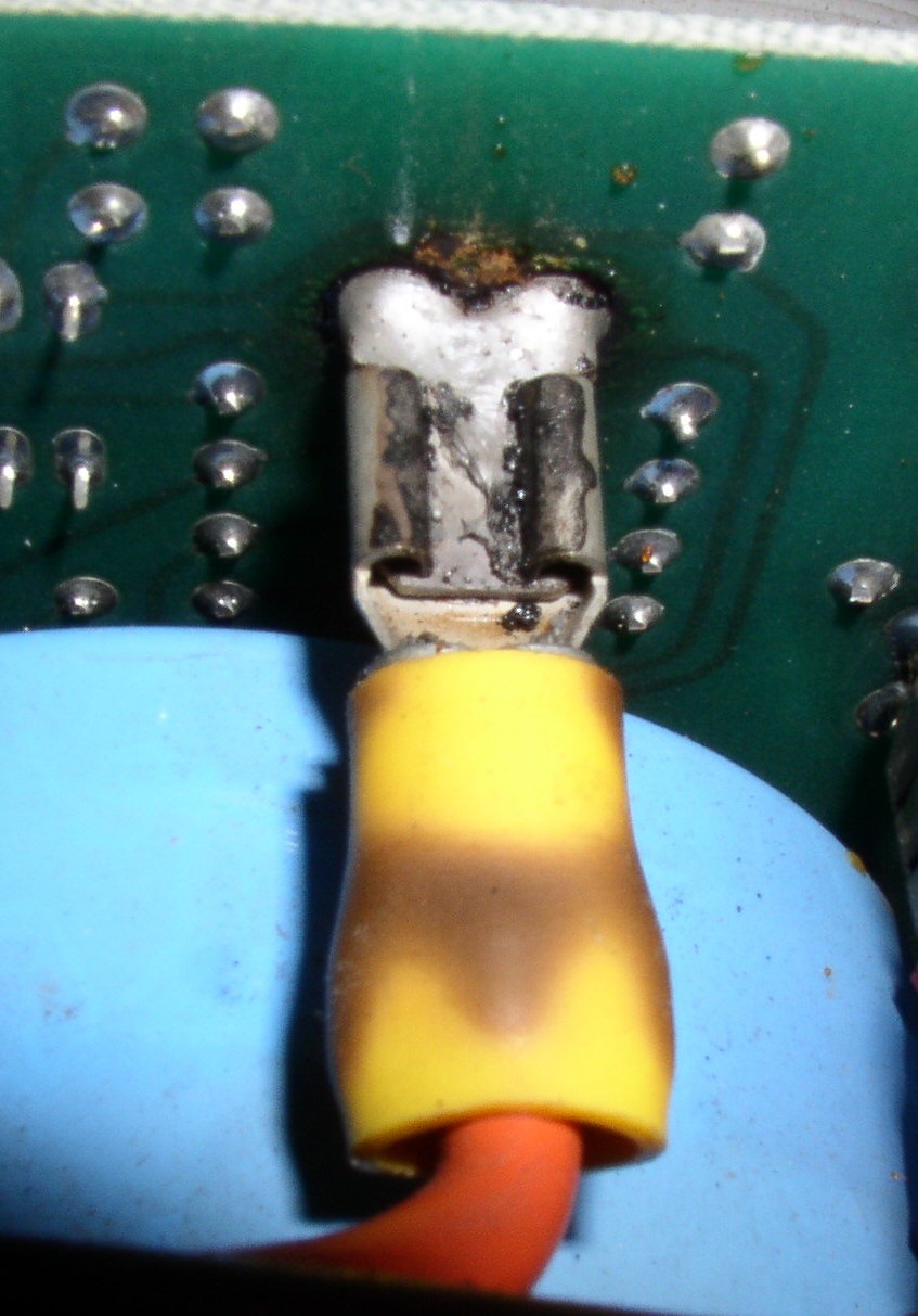
OK, next! As I mentioned, I have two systems I'm working on, and I'm starting
with the 11/23. It uses a Sigma BA11NL-1 chassis - very similar to the DEC
chassis of the similar id.
(Speaking of which... the chassis was in a box with a DEC "11L03-HA" label on
it - I can't work out if whoever owned it upgraded it with the Sigma [which
is Q22] or if DEC supplied the unit with the Sigma. I can't work out why DEC
would have used an outside supplier for that - unless either i) Sigma could
build a chassis much cheaper than DEC could, or ii) DEC was having supply
issues, and turned to Sigma to fill the gap.)
Anyway, so I've had it apart, and it's generally in very good condition...
with this exception in the power supply:
http://ana-3.lcs.mit.edu/~jnc/jpg/PDP11s/SigmaBurnedConnector.jpg
This spade lug appears to be the +5V common, although I'm too lazy to check
the prints to absolutely confirm that (there are two other similar wires
coming out of the transformer, but without the white stripe of this one, and
they both go to a honking great full-wave rectifier, the output of which goes
to a heat sink (!) which appears to be doing double duty as a bus bar).
Clearly, there was probably excessive resistance there somewhere, although
it's not clear if it was across the spade connector itself, or in the
wire-connector junction (note the brown spot on the insulating shield - I
first thought that indicated that the wire-connector joint was the problem,
but iff the spade connector got hot enough, the heat could have gotten into
the wire, and caused that spot).
So here's my question: what do I do? Do I:
- Pull the spade connector off, clean everything well (e.g. with a Dremel
wire brush), and put it back together, and hope?
- Replace the connector on the wire side only (slightly tricky, as there's
not much spare length in the harness, so I can't clip it off, I'd have to cut
the old one off with a Dremel wheel)?
- Try and replace the lug on the board too? (It looks like it got hot enough
to melt the solder - the solder has the surface crazing to it.) That might be
tricky...
- Do nothing and hope (on the basis that it didn't melt down yet :-)?
Whatever I do, of course, I should monitor it, and I'd like to avoid a lot of
grief replacing things unless I really need to, but I'm genuinely uncertain
what the best course is here. Thoughts?
Noel
Have a board here with subject chip on it. Also has 2 IMP-00A's. I assume
what I have is the 8 bit version of the IMP-16. Haven't been able to locate
instruction set for this 8 bit version. All the data sheet says is "CROM's
which implement 8-bit instruction sets are available as standard products."
Seems to be lots of info out there for IMP-16 but anyone heard of this
IMP-8A/521D?
Thanks,
Bill
Well, they do say that the device is there to protect the fuse...
http://www.classiccmp.org/acornia/tmp/fuse.jpg
Found in the chassis of an old 'scope. There's actually originally no
provision for a fuse in the 'scope itself - just a circuit breaker - but
quite why someone would take the trouble to cut a wire and then solder both
ends of the same fuse to it, I have no idea.
cheers
Jules
> From: Chuck Guzis <cclist at sydex.com>
> Do you mean something like the 2.54mm dual-row "Dupont" connector
> shells taking crimp pins?
> e.g. eBay 330875532644
Yes, that's it! How on earth did you find that? I looked on eBay (and then
Googling) for several hours, and couldn't!! :-)
> Paul Anderson <useddec at gmail.com>
> Do you need ones like used on the M7800 (DL11) and KL8?
> I have 20ma cables for these
Thanks; those are indeed the kind/size I'm looking for (quite a few DEC
boards use them), but I think I'm set now (above).
> John Wilson <wilson at dbit.com>
> the housing is technically 44 positions because it goes all the way to
> the edges, but the DEC connectors (like the IDC ribbon-cable
> connectors) skip the outer pairs so you only ever use the middle 40
> pins out of 44.
Interesting... I have a cable with 40-pin connectors (on an old IDE cable;
these are not keyed) and I tried plugging it in, and there is no space at all
on the sides (unlike, say, when one plugs a 10-pin shell into a 14-pin
DLV11-J connector). But looking at the connector carefully, I see that the
side arms of the top retainer piece take up space on the sides - looks like
just enough for a pin. So maybe the '40 pin' Berg headers really are
technically 44 pin size (although they do have only 40 pins).
Speaking of keying... does anyone know the name (let alone a source) for the
little plugs (usually white) that can go into one of the holes on one of those
connector shells, to key it so it can only go in one way round?
Thanks everyone, for all for the help!
Noel
> From: Tothwolf
> So was DEC using both AMP AMPMODU and Berg connectors for the cables?
Yup - and others as well - although seemingly not on the same board type,
though.
Pretty much all the 40-pin connectors I can see here (one a large range of
board types) have Berg on them (although it seems DEC was making the part
themselves under license, because all except one _also_ has a
"|d|i|g|i|t|a|l|" logo on it too); there is one DuPont. The non-DEC Berg and
the DuPont are absolutely identical except for the logo - and are on a pair of
cards which use them for an over-the-back connection, so I suspect they are
the same part, just re-labeled.
The 50's a a mix of Berg and 3M. There are 20's which are Berg. The ones on
the DLV11-J's (the one they gave the AMP part numbers for) aren't marked, nor
are a number of the other small ones.
Noel
> From: Tothwolf
> FCI bought out Dupont's connector division a long time ago, so what you
> are looking for is FCI's Mini-PV series.
> ...
> I'd advise against buying these type of contacts on eBay. 99% of the
> "Berg" or "Dupont" contacts on eBay are knock-offs and don't have
> decent plating (gold flash, if they have any gold on them at all) and
> aren't made to have the correct gripping force. .. they might not even
> fit a real HT-95.
Hi, thanks for all that great info. The 'gold flash' issue was new to me;
for those who are likewise unfamiliar with it, I found this nice write-up:
http://www.dfrsolutions.com/uploads/white-papers/Gold_Flash.pdf
Alas, I've already ordered some of the 'eBay knockoff' pins; when they get
here, I will look them over, and if poor quality, take appropriate action...
> From: John Wilson
> Digikey 3M9123-ND (3M 3435-0 "conn socket keying plug") is the version
> that fits into an IDC connector.
By pure chance, I later discovered, as I was reading the writeup on the
DLV11-J, that they gave AMP part numbers for the shell (10-pin, I assume),
contacts, and plug (they call it a "key pin"), and they seem to still work.
Here they are, if anyone has any use for them:
87133-5 Connector shell
87124-1 Contact
87179-1 Keying pin
How odd to find them in the DEC Interfaces Handbook!
Noel
Hi
I've found an old binary for the original TETRIS called TETRIS.SAV. I
believe it is a runnable binary made for RT-11 orginally run on of the
russian PDP-11 clones.
Now, I would like to run this under RTEM-11 on RSX-11M+, since that is
what I have available.
But I find very little documentation and I have no real idea how RTEM-11
works. Does anyone here with any experience want to give me some
pointers?
Simply, what do I do with an RTEM-11 installation and TETRIS.SAV?
Assume no or little knowledge on my side :)
/P
Hey, all, I'm looking for a source for 40-pin connector shells (to hold female
pins) for 2.54mm so-called Berg or Du Pont connectors. Anyone have a source
they can point me at? (I would call these male shells - since they go into the
female shells with male pins typically found on circuit boards - but I gather
the terminology is somewhat confused.)
The small ones (1-10 pins) are easy to find (they are used for audio/USB
connectors); the 40-pin females for use on ribbon cables are also easy to
find, as are the males that go into PCBs... but the 40-pin insertable pin
females appear to be unobtanium.
(I want them because a number of old DEC interface cards use them for cables,
and I refuse to pay $139 or whatever for a cable that's made of a total of a
couple of bucks worth of parts - I'm quite happy to roll my own.)
BTW, to quickly introduce myself (since this is my first message to the list);
I did a lot of work with PDP-11s 'back in the day', both as a software
development environment (using PWB Unix - roughly V6 - and later Ultrix), as
an application platform (multi-protocol routers, using LSI-11s), and also some
prototyping of high-speed network interfaces (1 and 10 Mbit/second rings).
I now have a couple of 11s (a 23 and an 84) which I'm trying to get running.
You'll be hearing lots more from me Real Soon Now as I get into that
project... :-)
Noel
Contacted you offline before I saw this. Thanks a lot.
Marc
> I'll see if I can get those disks imaged and uploaded somewhere in the
next day or two.
> -Glen
Howdy,
I've been having a good rescue year... earlier this year a PERQ, and now 2
Sun 1/100's (and yes, one is a 100, not a 100U).
(details of the rescues are getting written up for my blog at
http://www.vintagecomputerexpo.com... the first PERQ post is up already...)
With the Sun 1's I also got two tape/disk drive units... the first one
actually BOOTED the first Sun 1... first try (ok, 2nd try, after I
unparked the heads). The second actually does the initial boot but has
some hard read errors (so I'll have to give it a go with a
reformat to see if that resolves things...)
But the question I have is that the 2nd Sun 1 integrated monitor need to
have the vertical/horizontal hold adjusted. It currently
looks like someone tweaked the V-Hold and H-Hold dials that use to be at
least on my TV's :-)
On the outside there is only a brightness knob... so I'm going to have to
open it... but I've not been able to find any details on
what to look for... I'm assuming some potentiometers some place... does
anyone know?
Thanks.
Earl
I have a number of 16500 floppy disks I'd like to digitize, and am
wondering what the best way is to image them.
I will probably want to look at them if possible if they are FAT, as
some are, so having a flat image would be nice.
I'll look into the prior postings for software to image them for
reproduction.
I just tried a DD from one attached as an experiment in this way, and
did not get a good result:
Macbook Pro running Mavericks
Vmware Fusion.
Ubuntu 10
Teac USB floppy drive attached thru to the Ubuntu machine.
The floppy drive showed up, but a DD only copied in about 1mb from a
1.44 format disk. Not sure what quirk that was from. It's been a long
time, and even though I follow your discussions here, I'm not sure if
this pile will work.
I have a Linux Laptop and also a windows Laptop (XP) which I'm going to try.
thanks
JIm
Well, it's not so retro :)
I powered it up and seemed to work.
Booted from CD and removed root password.
While surfing in the HD, I got (console) a lot of ECC errors.
I powered it down and swapped two SIMM modules.
Then it refused to boot at all. CTRL-BREAK didn't respond in that phase.
So I rebooted and hit CTRL-BREAK early, and set diag-switch? true,
diag-level to max.
Resetted.
Got memory error, Ecache errors and RED state exception (may be I'm
missing something else...).
Did a lot of scrambling: memory modules, CPU modules (2).
Memory errors seemed to disappear, but Ecache errors remained for both
CPUs.
I noticed faults increase with temp.
Before I hit the wall multiple times with my head: shall I assume the MB
is gone fishing?
Ecache errors seems independent from CPU modules (I tried also 1-CPU
configuration).
I don't think a memory error (SIMM) could trigger and Ecache error (EDP)
on both CPUs.
Damn...
Thanks!
--
Vincenzo (aka Supervinx)
--==ooOoo==--
My computer collection:
http://www.supervinx.com/Retrocomputer
--==ooOoo==--
You can reach me at:
www.supervinx.comwww.facebook.com/supervinxhttp://www.youtube.com/user/supervinxhttp://www.myspace.com/supervinx
Glenn
I am super interested in a copy of these if it were possible. UPS just dropped a package with an HP1670G on my doorsteps a few hours ago (yay!) and I have an HP-IB and a 8085 probe on the way - but no inverse assemblers for either. Can I contact you off line?
Marc
>
> Message: 2
> Date: Wed, 10 Sep 2014 10:05:31 -0700
> From: Glen Slick <glen.slick at gmail.com>
> To: "General Discussion: On-Topic and Off-Topic Posts"
> <cctalk at classiccmp.org>
> Subject: Re: Reading HP 16500 Logic analyzer firmware disks
> Message-ID:
> <CAM2UOwLM5YNFgi8qOeadJZXS6v0weXdhZwpMg7PPwcACacqR3g at mail.gmail.com>
> Content-Type: text/plain; charset=UTF-8
>
> On Wed, Sep 10, 2014 at 9:53 AM, Sean Caron <scaron at umich.edu> wrote:
>> Has anyone archived Inverse Assemblers for various HP LAs anywhere? I'd
>> love to get the inverse assemblers for a few selected CPUs (68000, 6809,
>> 6502, Z80, ...) for my 1662A. Just stuff I'd be fooling around with while
>> breadboarding.
>>
>
> I have Config/IA disks for at least the following pre-processor interfaces:
>
> 10300B Z-80 probe
> 10304B 8085 probe
> 10342B HPIB/RS-232 probe
>
>
> ------------------------------
I just received a couple of the Cauzin Softstrip Readers, and after looking through everything included, there's no software to *create* my own barcodes! Does anyone have software that will let you print your own? I'm about to do a type-in BASIC contest starting tomorrow, and I thought it would be fun to offer the program in the softstrip format.
--
Follow me on twitter: @FozzTexx
Check out my blog: http://insentricity.com
I've been trying to familiarize myself with the soon-to-arrive SRAM board,
reading through the documentation, googling this & that, etc. But I'm
having trouble understanding a couple of concepts..
(You can d/l the manual for the board at http://nerp.net/~legendre/altair/
- "California Computer Systems 2016B". There's a pic there as well.)
I get that the S-100 memory space is organized into 16 blocks of 4096
(8-bit) bytes, with the high-order digit in the memory address denoting the
block number (0XXX-FXXX). This would correspond to address lines A12-A15.
Likewise, I get that the SRAM board is organized into 4 blocks of 4096
bytes per block, and that with the corresponding DIP switches, I can
individually map each 4K block into any of the 16 blocks in the memory
space. Great, I know how to configure the memory blocks..
But now what is this about 'banks'?
On p.33, section 3.3 the manual states "The 2016B is bank-selectable by
bank port address and bank byte. Thus it is fully compatible with Cromemco,
Alpha Micro and other port-bank-select systems. IT IS NOT COMPATIBLE WITH
ADDRESS-SELECT SYSTEMS SUCH AS IMSAI."
So what does that mean to me? There are apparently two parameters, Bank
Byte and Bank Port Address - and I just can't get what they're about. How
does a bank differ from a block, and why do I need to configure those
settings? And is this card even compatible with the Altair - I don't know
if it uses the former or latter (IMSAI) scheme..
As ever, thanks for your help!
>You don't get any sort of beep code out of it? I gather these 255/300s are
>supposed to beep at you like a PC does, given certain states where it can't
>produce a display (or, I guess, console output).
It cycles through the lights then stops there.
Based on your comments I pulled the NVRAM battery and then I get a 1-2-1
beep code that the manual calls "Real-time clock (BQ3287) failure, or the
real-time clock interrupt
did not occur." and the LED cycle stops at XX0X 0XX0 which it calls
"Interrupts test failed"
Still no output on Com 1 or on the video card (an S3 based VGA card).
My next thought is a new CR2032 and see if it get past that in the startup
sequence.
Any other ideas?
>Best,
>
>Sean
>
>
>
>>On Wed, Sep 10, 2014 at 3:59 PM, Sean Caron <scaron at umich.edu> wrote:
>>
>> Hi William,
>> Does it cycle through other LED states before it reaches 0xD1? Or does it
>> just start there at power-on and sit forever? That is pretty odd; not
quite
>> sure what to make of that. You tried the console with and without a
>> null-modem?
No null modem at hand. Just have a straight through cable and an Esprit
350C terminal.
Thanks,
William
--
Live like you will never die, love like you've never been hurt, dance
like no-one is watching.
Alex White l
> On Wed, 10 Sep 2014 08:56:52 -0700 Chuck Guzis wrote
>
> Indeed, if one looks carefully at the nonpolar crossover caps, they
> appear to be nothing more than back-to-back electrolytics. On the other
> hand, I note that motor run capacitors have gotten a lot smaller over
> the years, so a higher-voltage unit just might fit.
>
No one seemed inclined to recommend intermittent duty start capacitors so I've gone with high voltage run capacitors, all that seem available in the UK anyway.
As Chuck notes, things have got smaller. The originals (100uF, 60V) were 100mm long and 50mm diameter. The ones I have used (450V) are approx 120mm long plus a 12mm stud mounting and 60mm diameter. The TU56 has plenty of space although mounting them neatly without butchering the drive was a bit of a chore. Working satisfactorily - just the electronics to sort out now ;o).
Hello All:
I have a battery backed ISA RAM card by SemiDisk. It currently has a number
of Panasonic P-25AA 1.2V 250MAh rechargeable Nickel Cadmium batteries. Given
the card date backs from 1990 I am guessing the batteries are a bit dead and
I'd like to replace them. However, my Googlefu did not turn up anything.
Does anyone know if Panasonic still makes these batteries and if so where I
can purchase some in the USA? I did find some Chinese generic batteries:
http://www.amazon.com/Size-Rechargeable-Battery-250mAh-NiCd/dp/B005NRSQS8#
but I am not sure as to the quality of said battery. Any help is appreciated
in sourcing some batteries. Thank you.
-Ali