
8 Jul
2015
8 Jul
'15
9 p.m.
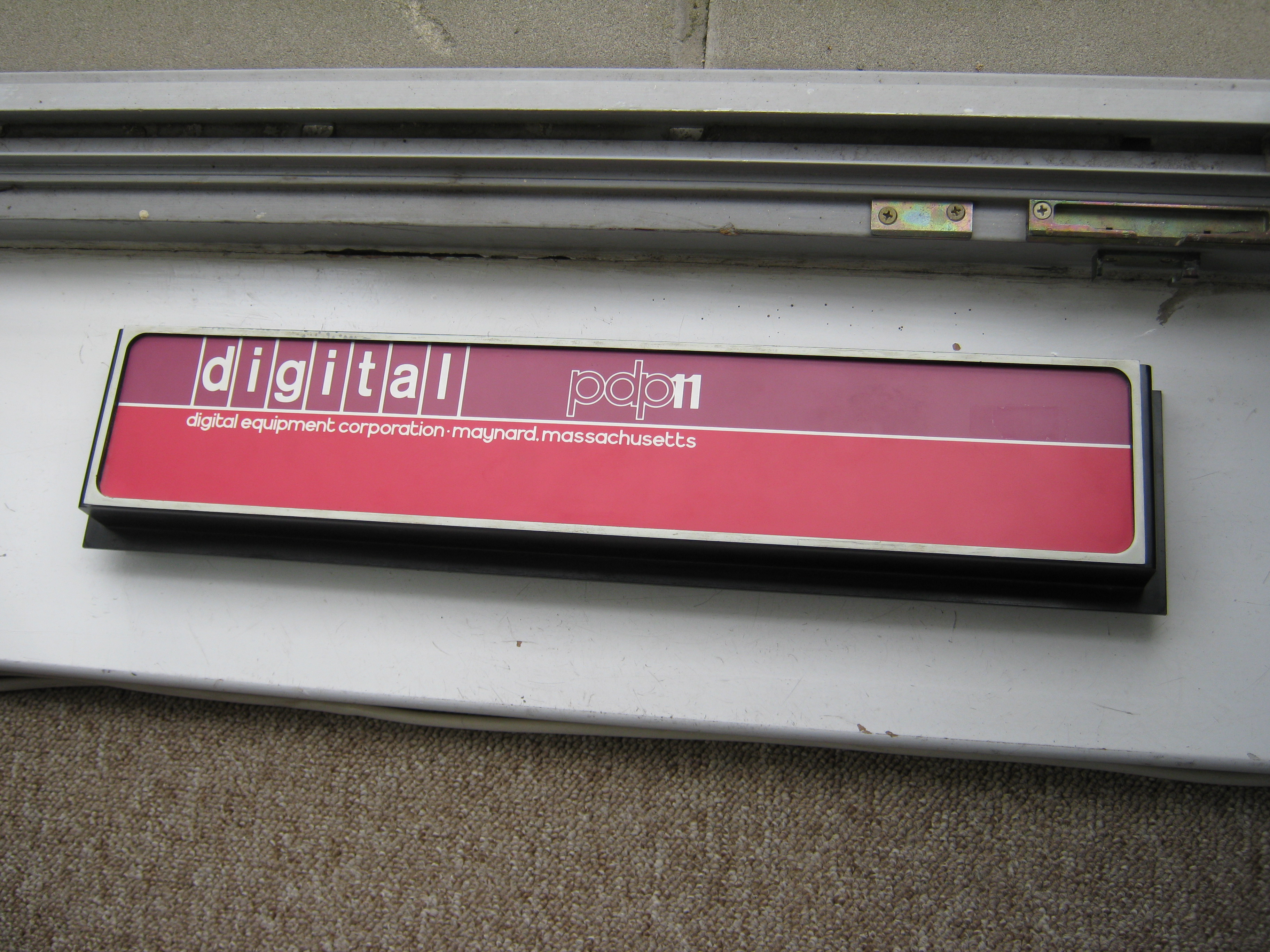
Following the recent discussion here on the 'DEC logo' topic, I've been
mucking about with my own efforts to produce a replica PDP11 masthead panel for the DEC
H960 rack.
The idea is basically to make an SVG for a vinyl stencil which looks 'good enough'
until I can find an orignal one. I've drawn CAD (vectors and arcs only - no splines)
over images I've found on the web, from scratch, without relying on the Batchelder
examples. So far the output is virtually complete but I need some help from the list,
if possible - I would like the dimensions of the width and height. I know it's larger
than a DEC filler panel. With thise I can adjust the drawing to the final size and
continue on the project.
As I need to mix a blurb with example images I've placed it under a blog entry on the
VCF board at
http://www.vintage-computer.com/vcforum/entry.php?544-A-good-enough-replica…
Please take a look, and thanks for any help or comments,
Steve.

9 Jul
9 Jul
2:52 a.m.
On 09/07/2015 05:00, steven at malikoff.com wrote:
Following the recent discussion here on the 'DEC
logo' topic, I've
been mucking about with my own efforts to produce a replica PDP11
masthead panel for the DEC H960 rack.
I need some help from the list, if possible - I would
like the
dimensions of the width and height.
I can do that today, and get you a few hi-res photos too. I've looked
at your blog page so I can see what you want.
--
Pete
Pete Turnbull

4:32 a.m.
On Jul 9, 2015, at 12:00 AM, steven at malikoff.com
wrote:
Following the recent discussion here on the 'DEC logo' topic, I've been
mucking about with my own efforts to produce a replica PDP11 masthead panel for the DEC
H960 rack.
The idea is basically to make an SVG for a vinyl stencil which looks 'good
enough' until I can find an orignal one. I've drawn CAD (vectors and arcs only -
no splines)
over images I've found on the web, from scratch, without relying on the Batchelder
examples. So far the output is virtually complete but I need some help from the list,
if possible - I would like the dimensions of the width and height. I know it's larger
than a DEC filler panel. With thise I can adjust the drawing to the final size and
continue on the project.
As I need to mix a blurb with example images I've placed it under a blog entry on the
VCF board at
http://www.vintage-computer.com/vcforum/entry.php?544-A-good-enough-replica…
Please take a look, and thanks for any help or comments,
Two suggestions: the 7-block digital logo you can take from the PostScript file, that
would be the authority for this. I expect you?ll need splines for that, arcs aren?t good
enough. And for the other text, the ?Handbook? font I posted should be correct. (In
fact, if any part of it is off, I?d like to know so I can fix it.) It has both variants
of the ?t? in it (and for the ?f? as well). Yes, for that one, arcs will suffice.
paul

12:35 p.m.
steven at malikoff.com writes:
I would like the dimensions of the width and height.
I've got one of these panels that came from the UKC machine room. I've
put some photos of it, along with a 600dpi scan of the front, here:
http://photos.offog.org/pdp11-panel/g/
The printed panel is 471mm x 84mm. The outer dimensions of the bezel are
480mm x 94mm. The panel's inset by roughly 4mm. The dimensions of the
rest are harder to describe, but hopefully you can get a reasonable idea
from the photos.
It looks like the bezel on mine has been repainted white at some point;
the rack it came from was still in use (with non-DEC kit in it) in 2008.
--
Adam Sampson <ats at offog.org> <http://offog.org/>
12:54 p.m.
On Jul 9, 2015, at 3:35 PM, Adam Sampson <ats at
offog.org> wrote:
steven at malikoff.com writes:
Nice photos.
Do NOT lose that Unix ?license plate?. The one you have is the original one, which was
made as an unauthorized project by Armando Stettner in the very early days of Unix support
at DEC. It?s rare. There are others that have a Digital logo on them somewhere which are
more common, and official, but not as interesting.
paul
I would like the dimensions of the width and
height.
I've got one of these panels that came from the UKC machine room. I've
put some photos of it, along with a 600dpi scan of the front, here:
http://photos.offog.org/pdp11-panel/g/
1:03 p.m.
On Jul 9, 2015, at 3:35 PM, Adam Sampson <ats at
offog.org> wrote:
steven at malikoff.com writes:
Now this is interesting.
On the inside cover page of the handbooks (say, the PDP11/45 handbook) you?ll find the
company name ?digital equipment corporation? with two different shapes for ?t?, with a
long bottom arc in ?equipment? and a short one in the others where there?s a letter to the
right. Similarly, the ?r? has a short arc in that text.
In the bezel as shown on the photo, the ?t? is consistently the long-arc version. And the
arc of the ?r? is longer than in the handbook.
Yet another oddity: that same handbook cover page has ?processor handbook? in the same
typeface. In that text, the ?r? have long arcs, longer than in ?corporation? on that
page, longer even than on the bezel of the photo. And while it makes sense for the second
?r? of processor, it looks weird for the first one.
Curious. It suggests that there wasn?t particularly close control over what the various
draftsmen could draw in creating those pages, or bezels.
paul
I would like the dimensions of the width and
height.
I've got one of these panels that came from the UKC machine room. I've
put some photos of it, along with a 600dpi scan of the front, here:
http://photos.offog.org/pdp11-panel/g/
12:58 p.m.
On 09/07/2015 05:00, steven at malikoff.com wrote:
I need some help from the list, if possible - I would
like the
dimensions of the width and height.
I've uploaded 14 pictures of the masthead to Flickr. Some of them have
a ruler (metric and imperial) included so you can not only see the shape
but accurate dimensions.
https://www.flickr.com/photos/pnt103/sets/72157655678560535
overall width 514mm
overall height 106mm
overall depth 57.0mm
distance from top edge to underside of mounting flange 12.7mm
box section width 493mm
box section/logo frame height 93.5mm
box section depth 33.1mm (from the back of the flange to the front of
the box, where the edge is rounded; the logo frmae extends 4.8mm beyond
that, and the )
logo frame width 480mm
coloured logo panel width 472mm
beige border width 4.0mm (all round)
box corner inside radius 9.5mm
depth of recess housing the silkscreen 4.0-4.1mm (it's not quite the
same in all the corners on mine).
The silkscreened logo panel is a separate component, and is a tiny bit
smaller - maybe 0.5mm -- I took a closeup of the bottom left corner to
try to show that.
hozizontal rule thickness 1.75mm (between upper and lower logo secions)
width of ascenders/descenders in "d|i|g|i|t|a|l" logo 3.7mm
height of "l" 23.6mm
height of "d" 24.2mm (the bowl descends below the ascender)
line width of boxes in "d|i|g|i|t|a|l" logo 1.75mm
line width in "pdp" logo 1.0mm
width of ascenders/descenders in "digital equip..." logo 1.2mm (1.18-1.21mm)
height of "l" 7.3mm
Note that there's a comma -- not a full stop (period) -- between
"galway"and "ireland" and I'm sure that's the case for
"maynard" and
"massachusetts" too, although it doesn't show well in the TU10 picture.
I've shown it in closeup in one of mine.
--
Pete
Pete Turnbull
1:14 p.m.
On 09/07/2015 20:58, Pete Turnbull wrote:
I've uploaded 14 pictures of the masthead to
Flickr.
overall width 514mm
[etc...]
There does seem to be some variation between reported dimensions, so
just in case anyone is wondering, mine were made with a 60cm certified
engineer's steel rule and a digital micrometer, with the aid of x10
loupe where necessary.
Maybe we're seeing batch variation and some of the dimensions have a bit
of a tolerance :-)
--
Pete
Pete Turnbull
1:43 p.m.
Pete Turnbull <pete at dunnington.plus.com> writes:
overall height 106mm
Note that the plastic moulding's actually different between Pete's
Galway panel and my Maynard one. The outer flange at the sides continues
around the bottom of the panel on mine, whereas it's cut away on Pete's:
https://www.flickr.com/photos/pnt103/19370727168/in/album-72157655678560535/
http://photos.offog.org/pdp11-panel/photo-ats-20150709T171733-IMG_3144.JPG
https://www.flickr.com/photos/pnt103/19562978651/in/album-72157655678560535/
http://photos.offog.org/pdp11-panel/photo-ats-20150709T171640-IMG_3141.JPG
--
Adam Sampson <ats at offog.org> <http://offog.org/>
6:21 p.m.
Wow, I wake up and you blokes on the other side of the world have been busy during the
night working at getting a bunch of details for me :)
Thanks Barry, Pete, Paul, Noel, Bill, Adam for your responses - the measurements and
photos are exactly what I need. I'll go through them in
detail soon and adjust the drawing.
Paul: I will revisit the postscript file and fix up mine from it. There's a reason I
try to avoid splines in my CAD drawings, a long time ago
I did DXFs for laser cutting some keyrings (see
http://web.aanet.com.au/~malikoff/jeep/keyring) using splines. The cutter operator
replaced
them with arcs owing to their software not being able to process it properly. Since then
I've avoided splines for any drawing I do that has a
chance of being exported as a DXF (or SVG for that matter) that is to be fed to a CNC
device.
I'll also follow up on your observation about the variations in the handbooks font,
I'm sure I'll find them on bitsavers.
Noel: fabulous! Thanks very much for the measurements, appreciate the use of calipers. I
do agree that efi is a great DEC seller, I've bought
some bits from him. I'll reluctantly pass on the blank panel though, our dollar is
weak and the international postage rates have gone through
the roof in recent times.
Bill: wood would suffice I guess, but unlike wood, styrene sheet always has perfectly
consistent working properties and as a long-time scale
modeller I am extremely familiar with using it. I also have a number of large sheets of
the stuff, in different thicknesses, ready to use.
Adam: I appreciate your photos very much. One thing that intrigues me is the end-on photo
IMG_3161. It appears the top edge projects further
than the bottom by a tiny bit leading to a tapered appearance, but I assume the plane of
the printed inset panel is parallel to the exterior
mounting surfaces. If you don't mind I'll load that into CAD and do some
overdrawing to determine if that's the case. Your lighting is good
so I'll take the RGB values for the colours. BTW the first image won't load for
me: '... cannot be displayed, because it contains errors'.
Pete: also teriffic photos, thanks as well! Nice measurements especially the letter
heights. That will be invaluable to make it a better drawing.
I think I'll need to do a drawing of the whole unit and then have the measurements
checked so I don't misinterpret your figures. Appreciate the
use of a micrometer too. A common method of determining radii is to use an engineers
radius guage. Failing that, try fitting a series of
circular objects (coins etc.) which can then be measured with calipers or micrometer.
So thanks again everyone, a super response.
Steve.
10 Jul
10 Jul
2:39 a.m.
On 10/07/2015 02:21, steven at malikoff.com wrote:
Pete: also teriffic photos, thanks as well! Nice
measurements
especially the letter heights.
Thanks, you're welcome.
A common method of
determining radii is to use an engineers radius guage.
Which is what I did :-)
--
Pete
Pete Turnbull
2:48 a.m.
steven at malikoff.com writes:
One thing that intrigues me is the end-on photo
IMG_3161. It appears
the top edge projects further than the bottom by a tiny bit leading to
a tapered appearance,
It's not tapered; it just looks that way because I'm not holding it very
straight in the photo. I've added a couple more end-on pictures that
should show this more clearly:
http://photos.offog.org/pdp11-panel/g/
BTW the first image won't load for me: '...
cannot be displayed,
because it contains errors'.
It's a pretty big image. If your browser doesn't like it, try saving it
and loading it in something else? I've added a lower-res version as well.
Thanks,
--
Adam Sampson <ats at offog.org> <http://offog.org/>
8:48 a.m.
On Jul 9, 2015, at 9:21 PM, steven at malikoff.com
wrote:
Wow, I wake up and you blokes on the other side of the world have been busy during the
night working at getting a bunch of details for me :)
Thanks Barry, Pete, Paul, Noel, Bill, Adam for your responses - the measurements and
photos are exactly what I need. I'll go through them in
detail soon and adjust the drawing.
Paul: I will revisit the postscript file and fix up mine from it. There's a reason I
try to avoid splines in my CAD drawings, a long time ago
I did DXFs for laser cutting some keyrings (see
http://web.aanet.com.au/~malikoff/jeep/keyring) using splines. The cutter operator
replaced
them with arcs owing to their software not being able to process it properly. Since then
I've avoided splines for any drawing I do that has a
chance of being exported as a DXF (or SVG for that matter) that is to be fed to a CNC
device.
Wow, it?s amazing that a device like that would be bothered by splines. It speaks to the
lack of competence on the part of the implementer. Perhaps this problem dates back to the
dark old ages of first generation cutters and has been cured by now? If not, you can
approximate things with arcs, but for it to look reasonably close to correct you need more
short arcs than you have now.
I'll also follow up on your observation about the
variations in the handbooks font, I'm sure I'll find them on bitsavers.
Not on bitsavers as far as I know (though Al is welcome to place a copy there if he wants
to do so). But you can find it on John Wilson?s site, at
http://www.dbit.com/pub/misc/handbook.ttf
paul

8:55 a.m.
On Jul 10, 2015, at 8:48 AM, Paul Koning <paulkoning at comcast.net> wrote:
Wow, it?s amazing that a device like that would be
bothered by splines. It speaks to the lack of competence on the part of the implementer.
Perhaps this problem dates back to the dark old ages of first generation cutters and has
been cured by now? If not, you can approximate things with arcs, but for it to look
reasonably close to correct you need more short arcs than you have now.
I think CamBam hates splines too, although it will load them and work with them, just very
slowly. I usually have to tell it to convert all splines to polyline approximations.
I?ve never had any problems with splines with the lousy software I use with my vinyl
cutter though. I load Illustrator 8 files and cut them without any issues.
--
Follow me on twitter: @FozzTexx
Check out my blog: http://insentricity.com
5:21 p.m.
I've adjusted the drawing based upon some of the measurements provided, so far.
However I'm not sure I interpret Pete's measurement of 33.1mm
from the back of the flange to the front of the box,
correctly. Noel also says the same 'from the back of the flange' so I must be
missing
something here.
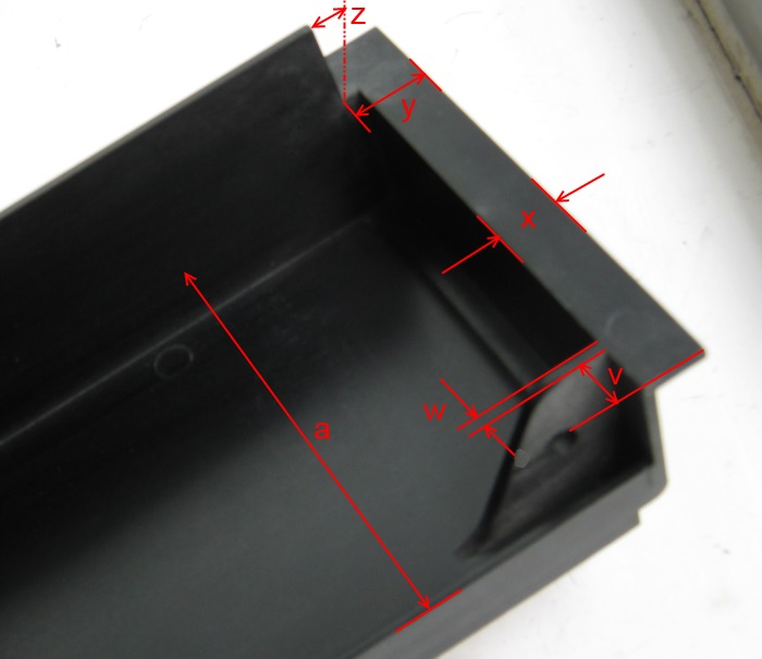
I'd like to get it as accurate as possible. So, I've taken some of Adam's
photos and annotated them with labelled arrows (hope that's ok Adam).
Would it be possible to get these? Hopefully this will clarify things. One or two labels
are repeated, I know:
http://www.surfacezero.com/g503/data/500/dimension_check-IMG_3161.jpg
http://www.surfacezero.com/g503/data/500/dimension_check-IMG_3162.jpg
http://www.surfacezero.com/g503/data/500/dimension_check-IMG_3144.jpg
Noel: thanks for trying the drill bits on the radius. From the original TU10 photo I
determined 9.6mm, Pete says 9.5mm so I'm not too far out.
I have adjusted it to 9.5mm anyway, along with most of the other measurements provided.
Paul: thanks for John's Handbook Truetype font. I've looked at it and (for me) the
kerning is not quite right even when using the narrow 't'
(0054, or ALT + keypad 83) also on other characters. To get the proper representation for
the panel I would need to convert the TTF word string
to an image or SVG path, shuffle the characters to the correct spacing and then reimport
it. So I'll stick with what I have for this. His 's' is
far better than mine though - I'll work on that.
Thinking about Chris' mention of vinyl cutting, the long horizontal line could be
dropped from the cutting image which would bring the length
down from the start of the |d| box to the end of the '11' ie. about 245mm which
would should(?) fit an A4 cutting space. The line could be applied seperately with
automotive or scrapbooking lining tape.
Thanks again
Steve.
7:04 p.m.
On 11/07/2015 01:21, steven at malikoff.com wrote:
I've adjusted the drawing based upon some of the
measurements
provided, so far.
I'd like to get it as accurate as possible. So,
I've taken some of
Adam's photos and annotated them with labelled arrows (hope that's ok
Adam). Would it be possible to get these? Hopefully this will clarify
things. One or two labels are repeated, I know:
"flush with bottom edge?": yes, it is.
b = 93.5mm at the position shown, but it's slightly tapered,
presumably for purposes of injection moulding. If you measure
it just above the flange (the part with thickness "i" in that
photo) it's 94.5mm. I'd not noticed that before.
d = 56.95mm
g = 4.93mm - 4.98mm depending on exactly where/how I measure it
h = 106mm
i = 2.46mm
j = 33.18mm
k = 11.67mm
L = 2.7mm where you drew the line, tapering to 2.3mm at the rear
edge (for injection moulding again)
m = 14.25mm
q = 15.5mm
r = 6.35mm (it's a 1/4" hole to clear a 10-32UNF machine screw,
which screws into a Tinnerman nut on the top crossmember of
the rack)
s = 11.1mm (hard to be absolutely accurate with the tools I have,
but that is suspiciously close to 7/16")
t = 27.9mm where you've drawn it. You obviously realise it goes
in further under the flange, radiused as shown in IMG_3144.
u = 11.27mm
a = 91.05mm (that's from upper surface to upper surface)
v = 9.21mm (average of two corners)
w = 2.53mm (this tapers as well, to 3.1mm at the base)
x = 12.25mm
y = 15.5mm (but on mine, the piece of the flange that y is the width
of, is almost 1mm wider on one side, but only in the part
hidden by the flange that Z points to)
z = about 0.5mm - you're trying to measure the taper on the edge of
the flange? Not easy to be accurate.
That flat part, across which you're measuring "x" and "y", looks
as if
it goes all the way across the bottom in IMG_3161 (where you've measured
"k") but it doesn't on mine. It only goes as far as you can see in
IMG_3144, and there are machining marks in the plastic where the rest
has been cut away - and from the look of the marks, they're in the mould.
Noel: thanks for trying the drill bits on the radius.
From the
original TU10 photo I determined 9.6mm, Pete says 9.5mm so I'm not
too far out. I have adjusted it to 9.5mm anyway, along with most of
the other measurements provided.
Bear in mind that as this was designed in the US, the design
measurements and tools were almost certainly imperial rather than
metric. So that radius was probably cut on the master with a 3/4"
cutter, rather than 19mm. That makes the radius 3/8", which is 9.525mm:
slightly larger than 9.50mm but closer to 9.5 than to 9.6. Though I
doubt anyone cares much about 0.1mm here, let alone 0.025mm :-)
--
Pete
Pete Turnbull
11 Jul
11 Jul
8:18 a.m.
On Jul 10, 2015, at 8:21 PM, steven at malikoff.com
wrote:
...
Paul: thanks for John's Handbook Truetype font. I've looked at it and (for me)
the kerning is not quite right even when using the narrow 't'
(0054, or ALT + keypad 83) also on other characters. To get the proper representation for
the panel I would need to convert the TTF word string
to an image or SVG path, shuffle the characters to the correct spacing and then reimport
it. So I'll stick with what I have for this. His 's' is
far better than mine though - I'll work on that.
It?s mine, actually; John provided the storage.
Thanks for the feedback, I?ll see if I can fix that. I created that font many years ago
using CorelDraw, which has a very primitive export-to-TTF feature. In particular, no kern
support at all.
paul
3918
days inactive
3920
days old
16 comments
5 participants
participants (5)
-
 ats@offog.org
 -
 fozztexx@fozztexx.com
 -
 paulkoning@comcast.net
 -
 pete@dunnington.plus.com
 -
 steven@malikoff.com