
29 Oct
2005
29 Oct
'05
5:05 p.m.
Background:
The problem with the old HP 9162-0061 data cartridges is that the
magnetic coating peels off from the (transparent) tape causing the
machine to stop accessing the tape with an EOT warning. This is
actually very good news because it means that the damage is localized
(a few mm of tape with scrapped off magnetic coating).
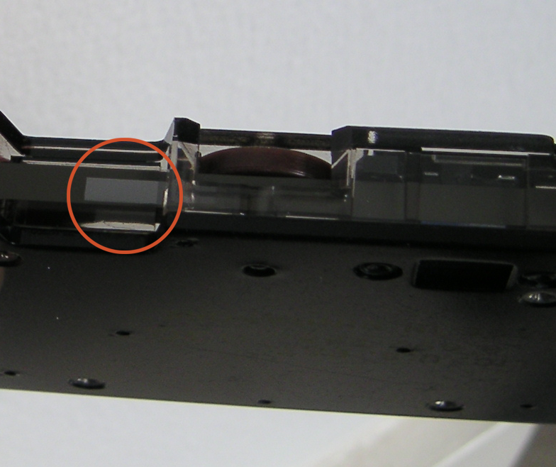
BTW here is a picture of a damaged tape:
http://www.series80.org/Articles/DamagedTape.jpg
My guess is that the magnetic coating gets scrapped off the tape
during fast motion (rewind or fast forward), so presumably if you
Hmmm. I thought it was where the taps stuch to itself, or to the drive
belt, when the catridge was stored. In which case your idea might not
help much.
simply advance the tape over the heads at normal read
speed (10 ips)
the tape will survive for a single pass (there are two tracks on the
tape, but since the head is not moving, I assume that you can read
both tracks at the same time).
I would think so. The head is not moved between tracks, it's electrically
switched.
Now since we have only one attempt, and we are likely to encounter errors,
I do not want to have the Series 80 firmware involved in the process.
I would like to simply record the info (via a PC) to a .wav file and then
process that file to see if anything can be extracted.
Proposal:
To do this I would need to manually rewind the tape till the BOT sensor,
mount it on the tape drive and advance it past the read/write head
till I run out of tape (tape unspools from the supply reel).
While this is going on I am recording the output of both heads via the
audio in port of my PC sound card (maybe use two separate sound cards to
avoid cross talk?).
I would think one sound card (with 2 input channels) would be enough. I
think cross talk would be pretty easy to eliminate in software (if it's a
problem at all).
Data extraction rig:
1) audio connection: what kind of set-up would be required to connect the
heads to the audio card. From the schematics I see that there are essentially
three connections to each head:
Head 0: H0, CT0, and HC
Head 1: H1, CT1, and HC (HC is common to both heads)
But I am not sure what these are used for.
I would assume 'Hn' was the top end of each winding, 'CTn' was a centre
tap and 'HC' was head common.
What I would do (and alas it needs a 'scope would be to remove the R/W
chip and connect the differential inputs of the 'scope to HC and H0
(say). Run a recorded, but unimportant 'scratch tape' through the thing
and see what signal you get. Then design a differential amplifier to
bring it up to the sound card input levels.
The preamp schematic from the 9815/9825 tape drive might be a start. Does
anybody know if those drives are tape and track compatible with the 85
drive? In other words, would the 2 track head of a 9815 correctly read
the tracks on an 85 tape (yes, I know the controllers are very different).
2) running the tape at a constant 10ips. There is a circuit that uses
the tachometer wheel to control the tape speed, but again I am not sure
how to program (?) the tape controller IC (U1) to move the tape.
(I may need to disable the BOT/EOT sensors, but that should not be a
problem).
Could you not design your own motor controller? It's 'just' a matter of
controlling the motor voltage to get the right frequency output from the
tacho sensor.
What I would do, actually, is extract the drive from a 'junk' 85 (or a
9815 or something if that drive is compatible) and use virtually none of
the HP electronics. Make my own motor controller and head amplifiers. I
would not want undocumented custom chips around. You might be able to use
the speed control circuit from the 9825, that is all standard chips
I am lucky to have a 9915A as my test bed which allows far easier access to
the tape drive mechanism than the HP-85 (and does not have these evil
ribbon cables).
Incidentally, there are some interesting manuals for the 9915 (and other
HP desktops) on http://www.hpmuseum.net . Even an operating/service
manual for the _keyboard_.
-tony