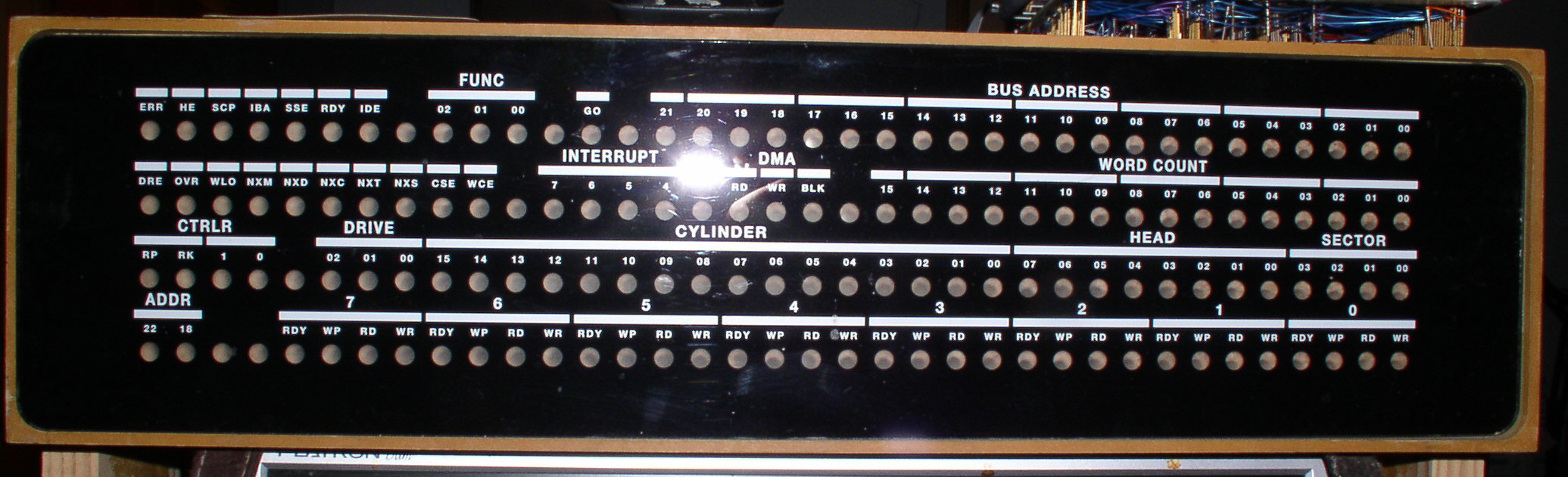
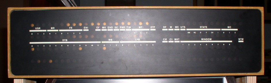
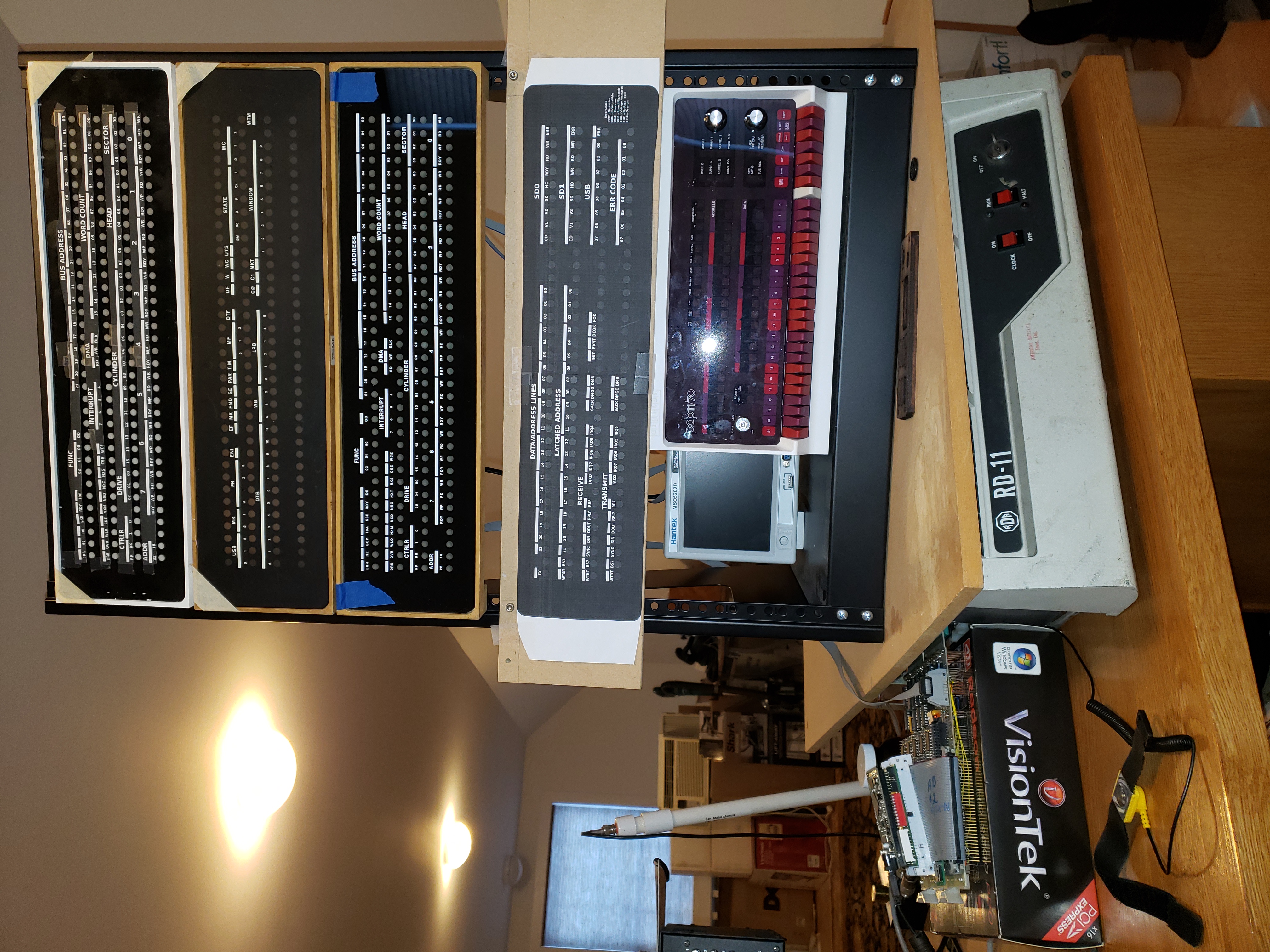
Hey all --
Got the TC01 working the other night, after a couple weeks of debugging
(*). I'd like to be able to have both it and the RF08 that I'm working on
connected to the 8/I and running at the same time, so I'm looking for a
DM01 Data Multiplexer. If anyone has any leads, do let me know.
Thanks as always,
- Josh
(*) Total TC01 fault count (so far):
- Bad transistor in TU55 motor brake control (W040)
- Bad jumper solder joints in TU55 (W990)
- Timing of UTS and U+M one-shots (R303) way out of adjustment (U+M
one-shot was at 2 seconds or so...)
- Bad tape data relay (G851)
- Bad IOT decoder transistor (W103)
- Missing Diode (W113) and weak diode in Write enable selection logic
- Timing of write clock way, way out of adjustment (90Khz vs. 125Khz
expected.)
- 24 dead maintenance panel bulbs
- 2 dead TU55 bulbs (yet to be replaced)
About the software:
I bought a couple of that seller's cards; one each of 284088568161 & 284088570014.
Asked him about the software. Here's his reply.
========
Regarding your question about the Analyzer software, if I recall correctly it comes bundled in the "NI-488.2" software package. I believe the version in my screenshot in the eBay listing was v17.6 for Win7 SP1 x86, but it should still be fully supported in the newest v21.0 package for x86 or x64 systems.
https://www.ni.com/en-us/support/downloads/drivers/download.ni-488-2.html
LabVIEW version compatibility matrix:
https://www.ni.com/en-us/support/documentation/compatibility/17/ni-488-2-an…
========
All new to me.
Now to hunt manuals for the cards.
Guy
At 12:33 PM 9/12/2021 -0800, you wrote:
>On Wed, Dec 8, 2021 at 10:50 PM Rodney Brown via cctalk
><cctalk at classiccmp.org> wrote:
>>
>> NI National Instruments PCI-GPIB+ Analyzer PCI IEEE488.2 Interface Card
>>
>> While a photo shows the Windows NI Analyzer software in use, the item
>> doesn't mention it.
>>
>> If NI will provide the analyzer software, these could be used to capture
>> HP-IB traffic to characterize the attached devices, timings etc.
>>
>
>Has anyone recently installed and used the NI GPIB Analyzer software?
>Is that something that must be obtained and installed separately, or
>is it included as an optional component of the standard NI-488.2
>download and installation?
>
>I suppose I could try downloading and installing the 1.19 GB current
>21.0.0 version of the NI-488.2 software to take a look. The current
>21.0.0 version of NI-VISA is another 1.11 GB download.
>
> From: Steven Malikoff
> Was there ever an indicator panel for the RC11? .. I have a set of RC11
> modules .. No backplane though. I've not found any docs for these, I suppose
> they're probably on bitsavers and have overlooked them.
Looking at the manual and engineering drawings (at BitSavers, as you guessed), no lights.
I've added links to those to the CHWiki RC11 page:
https://gunkies.org/wiki/RC11_disk_controller
The engineering drawings have the wirelist for the backplane, so it would be
possible to wire a new one. (I'm in the process of doing that for my KE11-A.)
Not sure it would be much use without an RS64 drive, though.
Noel
> From: Tony Duell
> I have _two_. But alas nothing to connect them to.
Well, there are still a good flock of machines with IBM channels around, but
_you_ don't have one (I can't blame you :-). I wonder if any of the people
with IBM channel machines have any need to connect to an -11?
Speaking of extant dinosaurs, I wonder if any RF11's still exist?
Noel
Many years ago, a friend gave me an Overland T490 tape drive which has
some kind of autoloader attached which takes ten tapes. I was told it
came out of a Tandem system. The tapes are square cartridges similar
but different to a DEC TK50. I can't find very much information about
the drive on the web but there are some hints that it might be compatible
with an IBM 3480. It powers up nicely and the fan works and after a
short pause, a green LED illuminates. There are only two buttons on
the front, "unload" and "format".
There are two DD50 connectors on the back. One had a terminator plugged
into it labelled "SCSI differential". The other had a ridiculously long
cable with DD50 plugs on it connected, lending further credence that
this is a differential (pre-LVD I expect) SCSI device.
I would like to get this drive working with my Alpha or VAX VMS systems
but I have never had any luck getting them to talk to it. Recently,
I tried a using a DD50-HD68 cable I found somewhere to connect it to
a differential SCSI card in my Alphaserver 800 but I could not get VMS
to see the drive. Not knowing what SCSI id the drive is likely to be
using makes it hard to know where to start looking for it.
There are no switches on the outside of the drive which could be used
to set the SCSI id so I opened it up to see if I could find any hints
inside. I didn't see anything that looked like it could be used to
set the SCSI id inside either. What I did find is that the interface
board had a connector labelled "SCSI differential" which had two short
lengths of ribbon cables plugged into it leading to the two DD50
connectors on the rear panel and another connector labelled
"SCSI single ended" with nothing attached. There were also two ten way
jumper packs which were labelled "DI" and "SE" on each side.
So, not having any luck with differential so far, I tried moving the
two jumper packs from "DI" to "SE" and moving the ribbon cable to the
"SCSI single ended" socket. I used a short, known good DD50-DD50 SCSI
cable to connect the drive to my VAX 4000-100A and replaced the
differential terminator with a known good single-ended terminator.
VMS didn't see the drive. VMS has a utility called scsi_info which can
be used to send a SCSI inquiry command and read mode pages etc. Trying it
against each unused SCSI id results in "device timeout" every time. The
system disk is on the same SCSI bus before the tape drive and a SCSI
scanner can be connected after it on the bus. Both devices work fine so
the SCSI bus cabling and termination is in good shape on both sides of
the tape drive. I've tried moving the system disk SCSI id from 0 to 1,
changing the initiator SCSI id from 6 to 7 and replacing the scanner with
a terminator in case there is any sort of SCSI id conflict but scsi_info
still doesn't show up anything that could be the tape drive.
Does anyone have any information about this drive, particularly
whether it should behave like a standard SCSI tape drive and what
SCSI id and/or lun it is expected to use or if there is some trick
required to get it to start talking? Maybe it doesn't like SCSI
inquiry commands?
Extra bonus points awarded for details on how to control the autoloader.
Maybe I did some damage to it when I was trying to get it to work when
I first got it?
Regards,
Peter Coghlan.
> From: Jay Jaeger
> Also, if someone (else, presumably) does up a replica of the indicator
> panel board (perhaps with the option to use LEDs, with some resistor
> packs that could be bypassed for lamps
Two points.
First,there's the question 'are you trying to produce something that just
_looks_ alike, or do you want something that's electrically compatible (i.e.
can be swapped in in place of an original'?
If the latter, it might be going to take a little work; it might not be just
'wire up some LEDs and go'. If you look at the indicator panel prints (pg.
190 of the RF11 prints), the incoming lines are tied to the base of a
transistor; its emitter is tied to ground, and the light bulb is wired
between the collector and +6.5V. This means, I think (I'm basicaly a software
guy :-), that one turns the bulb on by putting a voltage on the input, which
turns the transistor on, and current flows through the bulb to ground. (If I
have that wrong, will someone please orrect me?)
Given that the way TTL works is that 'logic' outputs actually sink currect
when their output is '0' (i.e. current goes _in_ the 'output' pin), it might
take a little work to make the right thing happen. Although maybe not;
looking at the RK11-C prints, it seem to drive the indicator panel straight
>from the output of normal gates. I _think_ what happens is that when a gate's
output is '1', the output's voltage floats high, and that's enough to turn on
the transistor (above) driving the bulb. (Ditto the request for correction!)
But the real issue with 'electrically compatible indicator panels' is the
wiring. In the originals, the flat cables that drive them are soldered directly
to the indicator panel board, and also to the paddle boards. So the _only_
standard interface location is the paddle boards.
I suppose one could put Berg headers on both the indicator panel board and
the paddle boards, and use a standard IDC cable betweenthe two...
Mention of the paddle board interface brings me to the second point: even if
one did produce electrically-compatible indicator panels - where are you
going to use them in a PDP-11 system? Not in the CPUs - those all had their
own front panels. The only PDP-11 devices which used indicator panels which I
know of were:
- the DX11 (I don't think anyone's got one of those)
- the RF11 (ditto - although Guy was discussing emulating one at one point)
- the RP11 (but the indicator panel is built into the controller rack there,
so if one has an RP11, one already has the indicator panel)
- the RK11-C (and several people who have those already have indicator panels)
I agree, the indicator panels look cool - but where are you going to use one
in a historical PDP-11 system?
Sure, one could use either a electrically-compatible or
non-electrically-compatible indicator panel anywhere you want, plugging into
some non-historical hardware, but.. (The non-electrically-compatible
indicator panel Dave did for the QSIC is initially being used in something
which emulates an RK11 and/or RP11, so there's some rationale for it.)
Noel
https://www.ebay.com.au/sch/m.html?_ssn=techparts2020&_nkw=%22PCI-GPIB%2B%22
NI National Instruments PCI-GPIB+ Analyzer PCI IEEE488.2 Interface Card
(~USD140)
Ebay item #
284088568161 Copyright 1998???? 183619B-01
284088565868 Copyright 2001???? 183619C-01
284088570014 Copyright 2005 ASSY192125D-01
While a photo shows the Windows NI Analyzer software in use, the item
doesn't mention it.
If NI will provide the analyzer software, these could be used to capture
HP-IB traffic to characterize the attached devices, timings etc.
The HPDrive project mentions the analyzer cards as being supported
https://www.hp9845.net/9845/projects/hpdrive/#hpdrive
> From the blog of someone who got a KB11-A working
It's Fritz Mueller's blog; at about the top of this page:
https://fritzm.github.io/category/pdp-116.html
he's just turned the machine on for the first time, and you can
follow as he chases, finds and fixes CPU problems. The KB11-C/D
of the -11/70 is _very_ similar to the KB11-A he was dealing with
(they are _basically_ the same CPU, with a cache, and other stuff
added on the other side from the CPU, on the KB11-C/D), so there
are probably some good lessons to be learned.
> dunno if Guy Steele
Ooops; sorry, Guy - the brain is starting to drop bits.
> if the particular machine the system is being built for has an FP11).
> Perhaps the later BSD versions look for the FP11 on startup, and adjust
> their behaviour appropriately, but I'm not familiar with them.
The way user code deals with the existence/non-existence of the FP11 is
pretty simple.
In C (other languages probably do something similar, but I only know about
C),one gives the '-f' flag to 'cc', and when 'cc' invokes the linker, on
machines which don't have floating point support, it uses fcrt0:
https://minnie.tuhs.org/cgi-bin/utree.pl?file=V6/usr/source/s4/fcrt0.s
as the machine language startup (the thing that calls main()) instead of
crt0. The difference is that fcrt0 sets the UNIX 'illegal instruction'
signal, in that process, to go to a handler which emulates the FP11
instructions.
In V6, as distributed, the binary of all applications which use floating
point are linked this way, so they will all run OK 'as is' on a machine with
no floating point (including those which don't suppport any kind of FP11,
such as the -11/40). When run on a machine with an FP11, there are no illegal
instruction traps, and that emulator code is just never used.
I'm not sure what the deal with BSD is, for machines without an FP11; fcrt0.s
is still included in BSD2.9, so maybe it's still using this approach. I have
this vague recollection that at some point, floating point instruction
emulation was added to the kernel, removing all the signal overhead, but that
might be a bogus recollection.
Noel
Would anyone like to make an offer on this AF01? It's a multi-channel
A/D converter for old pdp8 and pdp12's. I really don't think I need it,
I just pulled it out of my closet, and I don't want to put it back in.
Copy me off list. Complete, multiple MUX channels (16 A121's) the A704
and the op amp (A200)
Hi!
Some time ago, I got my hands on a DECtape II, though no tapes.
That'll change after a long time and in a few days, even multiple
tapes will come in.
With that drive, I started some first tests. It's PSU seems to be
all fine, providing stable 5 and 12 V.
It's board's wire wrapping is in factory settings, so baud rate etc.
is all known.
However, when I checked the two drives capstans, they're old. One
has a crack, and as things go, they feel partially either hard or
gooey. Are there recommendations to exchange these for new ones? I
also noticed that one of the two motors rotates quite freely
(both unconnected from the board, so I'm sure they're not magnetically
braked) while the other ... can be turned without any unreasonable
torque, but it won't continue to spin at all.
Also, when the tapes arrive, are there recommendations in case their
drive belts are gone?
And a final question: There are three firmware versions archived for
the TU58 control board. It's a known version:
jbglaw at charon:~/customers/Glaw/VAX/DECtape II$ md5sum *.bin | sort
0e5f30a960e72c9d64174a4da8f48f50 23-294E2-00.bin
5e059396f779aef9cd80bc75a36c90b2 23-089E2-00.bin
5e059396f779aef9cd80bc75a36c90b2 jbglaw-DECtapeII-ROM.bin
a407fbb5aaa4823a92dd2bc374d1d3ae 23-389E2-00.bin
I guess I got the oldest version? Were there board changes, or could I
put in a compatible 2Kx8 ROM with any of these versions? I guess any
firmware will probably work "good enough", but if I'd avoid known
problems (are the differences known?), I'd rather avoid them.
But after all, I'm quite happy that all the bits'n'pieces will come
together in a few days. Yay!
MfG, JBG
--
> From: Rod Smallwood
> Let me see what artwork I have
I'm curious as to what you'd be able to find. Like I said, I'm pretty sure
DEC never did an RK11-C inlay; the engineering drawings for the 19" indicator
panel (included in the RF11 engineering drawings:
http://www.bitsavers.org/pdf/dec/unibus/RF11_EngrDrws_Oct70.pdf
on pp. 187-188) list many inlays, but not an RK11 one. Also, I've looked
through the RK11-C manual:
http://www.bitsavers.org/pdf/dec/unibus/RK11-C_manual1971.pdf
but it contains no mention of an indicator panel, which it surely would if
there was one.
> From: Henk Gooijen
> I have *two* DX11 front panels with the 144 lamps & 4 'paddle'
> connections boards. ... Given you have 144 lamps panel with the RK11-C
> front, what would you do to light up the lamps?
Uhhh... plug the paddle boards on the end of the flat cables from the
indicator panel into the pre-wired slots in the RK11-C backplane (see the
RK11-C engineering drawings:
http://www.bitsavers.org/pdf/dec/unibus/RK11-C_schemFeb1971.pdf
pg. 36)? :-)
Hence my comment that to make use of the _inlay_ I proposed to produce, one
had to have an RK11-C _and_ a spare DEC indicator panel...
Noel
Eric,
I would qualify that statement and say - I'm the Tek computer Monty :)
I have a Tektronix 4052 and 4054A, plus two Tektronix 4041 (68000 based
GPIB controller) computers :)
Both the 4052 and 4054A also have Tektronix 401x terminal emulation at up
to 9600 baud, so I don't have a use for the Siemens terminal.
Monty
On Wed, Dec 8, 2021 at 12:58 PM Eric Moore <mooreericnyc at gmail.com> wrote:
> Holy shit Monty, you are the tek terminal Monty.
>
> I just posted on facebook in the tek 4051 basic group, do you know anyone
> with a tek 41XX or 42XX terminal?
>
> -Eric
>
>
> On Wed, Dec 8, 2021, 12:51 PM Monty McGraw via cctalk <
> cctalk at classiccmp.org> wrote:
>
>> I have this terminal in my garage - sitting on its custom stand.
>>
>> I purchased it years ago, but don't have a use for it.
>>
>> Here is my photo of it:
>>
>> https://drive.google.com/file/d/1SV4-Xx7XLHIoA898ZPRC74wZv2e8YsVK/view?usp=…
>>
>> I'm near Houston Texas.
>>
>> It is too big and heavy to ship.
>>
>> Monty McGraw
>>
>
> From: Marc Howard
> I've got an 11/40 I'm going to start working on. Problem is that there
> are two power supplies (H742 and H7420) that came with it but neither
> was mounted in the rack.
-11/40's in general only have one of those large H742x suppplies in a rack.
The documentation and prints all show only a single one - in fact, the 11/40
power harness (which is specific to the KD11-A backplane, at the CPU end) can
only attach to one. The KB11 machines (-11/45 and /70) use two, but their
harness has provision for two.
I don't know of a DEC document that lists the difference between the H742 and
H7420, but my CHWiki page for them:
https://gunkies.org/wiki/H742_Power_Supply
gives what I think is a pretty good list; any errors or missing details would
be appreciated.
> Also how is the power cabling routed (I think I'm missing this part)?
That's going to be a hassle, replacing the main harness! Especially since
production of the 8-pin MATE-N-LOK connector shells used to interface to the
H744/etc 'bricks' - part numbers here:
https://gunkies.org/wiki/DEC_standard_modular_regulators
are out of production, although some vendors have residual stocks. Hoard them
while they last!
The "PDP-11/40, -11/35 (21 inch chassis) system manual" (EK-11040-TM-002):
http://www.bitsavers.org/pdf/dec/pdp11/1140/1140_SystemManual.pdf
has pretty good coverage of the harness; the back end of Chapter 6 covers it
in detail. That's a lot easier to understand than the FMPS:
http://www.bitsavers.org/pdf/dec/pdp11/1140/PDP-1140_System_Engr_Drawings_R…
so read that before you tackle the prints.
Note that there are two different kinds of harness, depending on whether the
machine has MM11-L (-15V) or MM11-U (+20V) core memory. Unless you're
planning on using one of those, you can probably ignore that, though.
Any questions, ask here right off; we have a lot of expertise! :-) ('My'
first -11 - as in, one I was in charge of - was a -11/40. Fond mempries!)
Noel
Marc: Do you have the 11/40-specific wiring harness? Assuming that you do it's a bit tricky -- not so much mounting a given supply (aside from the fact that they are heavy and awkward to work with even when minimally populated), but because there is a very tight tolerance between them to thread the wiring harness. I've determined the hard way that you really need to install the lower one first, then the harness, then the upper one. At least for me it wasn't practical/possible to install the harness after-the-fact. There's also a bit of work involved in threading both of the AC power cables plus the pair of power-control cables (assuming that you're using a DEC power controller) via the right-side vertical rack channel -- which also interact with the power harness placement. Once everything is cabled-in-place the result is maximally compact, but getting there is not simple. Yes, the power cable wiring isn't well-described anywhere IMO. You have to stare at the puzzle-pieces for a while and "dry fit". Harness shape/stiffness helps eyeball how to fit the pieces together, but the importance of the rack vertical side-channel in making everything fit is not, IMO, made at all clear anywhere in the various documentation -- although it can be inferred from careful examination of a few graphics in various documents. The 11/40, the 11/45-50-55, and the 11/70 share the same design in this respect so documentation for one will serve you well in any of these cases.
If you can tackle the task *before* installing the BA11 chassis you'll find it easier.
If you're not using a standard DEC rack or don't have an equivalent vertical side-channel to work with then IMO you'll need to get very creative ... and the 11/40-specifics wiring harness may not work at all and you'll need to build your own. Fortunately I didn't need to explore that path ...
Good luck!
-----Original Message-----
From: cctech <cctech-bounces at classiccmp.org> On Behalf Of Marc Howard via cctech
Sent: Saturday, December 4, 2021 10:28 PM
To: General Discussion: On-Topic Posts Only <cctech at classiccmp.org>
Subject: Need picture of power supply mounted in 11/40 cabinet
Hi,
I've got an 11/40 I'm going to start working on. Problem is that there are two power supplies (H742 and H7420) that came with it but neither was mounted in the rack.
Could someone post/send/etc. photos of how the power supply mounts in the rack? Also how is the power cabling routed (I think I'm missing this part)?
Thanks,
Marc Howard
Power Supplies, due to their Weight, are placed at the bottom of Racks (prevent tip overs / weight distribution).
https://avitech.com.au/?page_id=366
The PDP-11/70 Maintenance and Installation Manual (EK-11070-MM-002) explains that the basic PDP-11/70 system components are located in a double cabinet as shown in Figure 1-1 of that manual.
https://i0.wp.com/avitech.com.au/wp-content/uploads/2016/05/major-assemblie…
greg
> Date: Sat, 4 Dec 2021 19:28:01 -0800
> From: Marc Howard <cramcram at gmail.com>
> To: "General Discussion: On-Topic Posts Only" <cctech at classiccmp.org>
> Subject: Need picture of power supply mounted in 11/40 cabinet
Let me get this out before the list gets shut down _again_...
There is discussion of doing a run of indicator panel inlays:
http://ana-3.lcs.mit.edu/~jnc/tech/DECIndicatorPanels.html
for the RK11-C (which is wired for an indicator panel, although as far as
I know, DEC never did the inlay).
If you're interested... you will need a standard DEC indicator panel light
panel (with flat cables with plug-in-cards on the ends). (I don't have any
insight on how to get one of those. It shouldn't be _too_ hard to make
replicas, but I'll leave that topic for the moment.)
All I am proposing to do is create the silk-screened inlay that turns a DEC
indicator panel into an RK11-C indicator panel (starting with a functional
indicator penel without the inlay).
All DEC indicator panels use the same actual light panel and flat
cables/plug-in-cards (which have one conductor per light in the light panel);
which light comes on is set by the way the backplane slots the
cables/plug-in-cards plug into are wired.
So from the prints, which give the wiring to the indicator panel slots, I
managed to work out what an RK11-C panel would look like, roughly (captions
are made up, but the light locations are accurate):
http://ana-3.lcs.mit.edu/~jnc/tech/pdp11/RK11-C_inlay.txt
Starting with that, Dave Bridgham managed to whip up a rough approcimation of
what the inlay would look like:
http://pdp10.froghouse.org/qsic/inlay-rk11-c.pdf
We had put a certain amount of work into identifying a font which looks like
the one DEC used, back when; I worked with a member the UK to produce a bunch
of blank inlays (right size/shape, with the black paint on the back with the
holes for the lights). Dave then found someone who could print the white
lettering on the front, and this is what the result looked like, on an
'RK11-F' (the QSIC with RK emulation microcode) panel:
http://ana-3.lcs.mit.edu/~jnc/tech/QSIC/jpg/RK11F-F.jpg
You can compare with an original DEC inlay (TC08, IIRC) here:
http://ana-3.lcs.mit.edu/~jnc/tech/QSIC/jpg/DasBlinken2F.jpg
That's on the same light panel, just the inlay is changed. (The lights in the
lower one are from the light panel Dave produced for use with the QSIC; it's
totally incompatible, electrically, with the DEC originals; 4 wires, IIRC, run
the whole thing (data, clock, latch and a ground), as opposed to the 'wire per
light' of the DEC originals. Looks _just_ like the originals (which Tech Sq
used to have a lot of, BITD), though.
Anyway, if anyone is interested, the next step would be to find out who all
wants an RK11-C inlay, and work out _exactly_ what would be printed on it.
Noel
>
>
> From: Josh Dersch <derschjo at gmail.com>
> Subject: Source for DEC TC01 (and similar) bulbs?
>
> The Search Scope loop diagnostic shows block numbers going by in both
> directions so a lot of the drive and controller are working, but there's
> some glitchiness in bits 2, 5, 8, and 11 of the data so I need to trace
> that down; I hope it's not the tape head.
>
> - Josh
>
So what do bits 2, 5, 8, & 11 have in common? All bits come from the same
track on the tape head, and share some of the path to the Data Buffer.
If you wrote this tape on this system, I would try reading a tape that was
written on another machine to make sure that the problem didn't originate
with writing.
Check for a bad connection where the tape head cable connects to the G851
module in the TU55, where the G851 plugs into the TU55 backplane, and where
the data cable plugs into the TU55 backplane, and possibly the K2 relay on
the G851.
In the TC01 you could swap the G888 module in slot C22, the S205 module in
slot D05, the S205 module in slot E06, the S603 module in slot C02, or the
R123 module in slot E08, with another one to see if the glitch moves to
another bit.
--
Michael Thompson
I remember seeing this somewhere. I have done a fair amount of googling
with no luck.
I'm looking for a hand tool with a plyer like grip at the top of a shaft.
At the bottom of the
shaft there is a "foot" that, when you squeeze the grip, scissors open. The
idea being
that you slide the foot down between a daughter card and the motherboard it
is stuck in
and when you squeeze the grip, it lifts the card out of the slot. Anybody
know what this
tool is called and/or where to get one?
Thanks,
Bill S.
--
This email has been checked for viruses by Avast antivirus software.
https://www.avast.com/antivirus
On Mon, Dec 6, 2021 at 9:42 AM David Bridgham via cctalk
<cctalk at classiccmp.org> wrote:
> The inlays are mostly not done with any tools I have. I do the graphics
> with Inkscape. Rod made up the blanks with silk screening. Then I have
> the white printing done at a printshop I found who has a large, flatbed
> printer that can print white ink. I do have some ideas about how I
> might try to make up blanks with a laser etcher I have access to but at
> the moment we have an ample supply.
Cool.
> Also, I've experimented with making my own bezels out of PVC board from
> Home Depot using a CNC router. In the pictures below, the yellowed
> bezels are old DEC bezels while the white ones are ones I made. I
> figured that if we ever get the QSIC shipping and people want indicator
> panels (I hope they'll want indicator panels), I'd rather not depend on
> them ripping apart old DEC bezels to make this work.
Yes. I'd rather not demolish my only indicator panel. I was planning
on demolishing a blank (I have a few short blanks, but most people do
not)
> Anyway, I'd be most happy to have another person with more tools to help
> build bits and pieces of this stuff. I've noticed that as I gained
> access to different tools, I came up with different ideas about how to
> make things. I didn't think the laser etcher was all that useful until
> I started using it.
I have a small 40W laser etcher that I essentially haven't used since
I have had access to large-format 80-120W laser cutters.
As for tools, I can rent a 4'x8' Shopbot router at our local
Makerspace that can turn out the light blocking bar or, from your
file, the frame. We also have a local company (IC3D) that makes
cubic-meter 3D Printers and makes their own filament from pellets,
keeping costs down. The founders are friends of mine and I've helped
repair sensors on their manufacturing line. If I had an STL, I could
get a bid on what it would take to 3D print one. It wouldn't be as
smooth as a machined PVC foam milled one, but it would be strong.
With a little post processing, a 3D Printed frame may give an adequate
look. Just a possibility. I haven't worked with PVC foam much but I
understand the principle.
> Now I want to use it for everything. Turns out it
> can't quite handle 3/8" Delrin; it just melts it and makes a mess.
That sounds like a power problem. Normally, Delrin lasers quite
nicely, at least at 80W. Thick stuff is hard in any printer because
of lenses, beam diffusion, etc. We sometimes have problems with 1/2"
material of any kind in ours. I've done some stuff in 2 passes, one
high, one low (refocusing/repositioning Z axis between job runs). We
also have multiple lenses for different focal points. One is only
good for etching/surface work, and one is good for cutting 3/8" and
thicker materials. We usually use the middle one since 99% of what
goes into our laser is 3-6mm stock.
> Speaking of help, if anyone wants to review the QSIC design, I'd welcome
> that. This is by far the most complex circuit board I've ever designed.
I could take a look at it, I have some background in making Qbus and
Unibus interfaces, but how useful I'd be depends on what kind of
feedback you are looking for.
> Back to indicator panels, here's a picture showing a bit of the
> evolution of my indicator panels...
>
> http://pdp10.froghouse.org/qsic/indicator-panel-stack.jpg
>
> ... The only real thing I'd like to
> change is the gloss. Somehow, DEC's inlay is as flat as flat can be.
I did notice that. I have no idea what to recommend. AFAIK, DEC just
used an acrylic with a specific surface texture. The only stuff I can
get is like what you have - smooth as window glass.
Cheers,
-ethan
On Sun, 2021-12-05 at 12:00 -0600, Brie wrote:
>
> He may as well have just come out and said, ?It triggers me and I
> don?t like having to acknowledge that women exist in the field of
> computer history.?
>
> ? Brie
Sorry to go off topic, but I have friends and family who are veterans
or otherwise have had horrible experiences. They get triggered. What
this sentence is describing is someone getting mildly annoyed.
Does anyone recognize the (presumably) DEC power supply on the front half of
the rack-bottom in the 11/44 listing at:
https://www.ebay.com/itm/363640137050
Blurry photo, but it looks like there are a 4x3, a 3x3, and a 3x5 Molex
connector, and two brown mini-modules protruding from the right side.
If so, then what purpose did it likely serve?
It appears that the 6U immediately below the 11/44 was likely occupied by an
RX02 given the presence of an M8256 in the 11/44 backplane (and skinny
mounting rails, although I thought those were usually at the bottom of the
RX02), and that included its own power supply (which wasn't very beefy
either, nor did it need to be).
What went into the 6U immediately above the power supply is unclear; there
is a HEX Wespercorp TC130 Tape Controller as well as three unknown QUAD
modules in the 11/44 backplane. Perhaps there was a horizontal autoload
tape drive mounted there that required a separate power supply?
Curious!
paul