While this post is specifically for Tim Shoppa (as the only
person that I can think of who can answer), if anyone else
has the background, please reply.
I believe that I have found a rather inconvenient bug in
SDHX.SYS from version Y01.16 (from V05.06 of
RT-11) that can cause RT-11 to crash. If I am not
mistaken, the same bug is also present in the previous
version V01.00 of SDHX.SYS from V05.05 of
RT-11. Unfortunately, the bug can cause RT-11
to crash
There also seems to be another bug which results in the
extended memory status being displayed incorrectly,
but otherwise does not cause an actual problem.
I realize that RT-11 is rarely used these days and that
SDHX.SYS is used even less frequently, but I suggest
that these errors really need to be fixed. I would
appreciate any suggestions as to how to proceed.
Jerome Fine
So it turns out the NatSemi NS23C QBUS memory card can really, really easily
be upgraded from 256KB to 1MB, as it has all the necessary traces, jumpers,
etc for this capability built into the card - even though the NS23C
documentation says nothing about this capability!
I found out about this capability when I bought a group of QBUS cards which
included two NS23C cards. Looking at the chips, trying to figure out how big
the cards were (I didn't at that point know the card model), I saw one had
64Kx1 chips, the other had 256Kx1 - one was 256KB, the other 1MB!
Later, looking at the prints, I noticed that the memory chips had all 9
address lines wired (unlike the very similar NS23M card), and there were a
couple of jumpers that appeared to adapt the card to 1MB operation.
So I tried upgrading the second card, and it worked!
The chips are all in sockets, so pulling the 64Kx1's and replacing them with
256Kx1's was easy. There are three jumpers one has to remove/move; alas, they
are in the PCB on the top surface, although there are jumper pins there -
there's a trace running between the two pins - so you have to cut the traces.
The first two jumpers one has to remove are W23 and W24 (right next to the
other memory size jumpers), which allow one to increase the maximum memory
size to 1MB.
The other jumper one has to move, is to move the 'jumper' from W40 to W41;
this moves the pickup point for the 'RS0' signal, which indicates which bank
of chips (there are 2x18 banks, i.e. 16 data, and separate byte parity) to
activate, from address line 17 to 19.
(Parenthetically, the way the address logic works on the card is slightly
odd; if the card is not on a 'natural' boundary [e.g. a 256KB boundary, if
it's a 256KB card], the memory contents are scrambled; the low memory, in bus
address terms, is at the top of the card, in chip terms, and the high memory,
in bus terms, is at the bottom of the card. I understand why they did it that
way, it's the most economical in logic/traces, etc but it's something one
would have to remember when looking for a bad memory chip, if the card is set
to an address which is not a multiple of its size.)
Not sure if anyone else out there has any of these cards, but if so, I'd be
interested to hear if anyone does this.
Noel
I have scanned and uploaded 12 issues of "Kugram," the official
newsletter of the Kaypro Users' Group:
https://archive.org/search.php?query=kugram&sort=-publicdate
It's really "K?gram," which I'd say as "K-microgram" but the limits of
character sets and convenience probably turned it into "koo-gram."
And they refer to themselves as "kuggers," not "K-microgrammers." :)
One odd thing about these: there's no date on the covers, just Volume
and Issue numbers. However, it looks like they started publishing in
January 1983.
Anyone got any more issues laying around that I can add to this
collection? I will pay for postage to get them to me. You can have
them back, but I will have chopped their spines for easy scanning.
Also, anyone want the physical copies of the ones I've scanned? Pay
the postage and I'll send them out (there are two copies of a few of
them.) They are chopped as well.
Enjoy!
-j
I have an RK05J drive that has been sitting around for a long time, and I want to prepare it for going back into service on my PDP 8/e system.
Here's what I've done so far:
- I have replaced the foam that isolates the blower motor from the housing, as it had started to deteriorate.
- I vacuumed out the entire drive very carefully
- I removed the head-lock that was put in when the drive was transported from its original location to my location
- I ran the drive without a cartridge (and not connected to a system) for about 6 hours with the old absolute filter in place
- I removed all of the circuit boards and cleaned the edge connectors and sockets
- I tested all of the front panel lamps, and found all to be good
- I replaced the absolute filter and ran the drive for another few hours to circulate air and get any last particles of stuff filtered out.
- I very carefully cleaned the heads... they were extremely clean. I used a lint-free swap, and a commercial solution that I have that I've used for floppy disk head cleaning that seems to work well. I used this solution on the first RK05's heads, and it worked with no problems. However, the first drive was in service on the PDP 8/e when I got it, and was running fine. This second drive came off a PDP 11 system, and has been sitting for a very long time (years).
I plan on running the drive without a pack in it for about 2 hours before I try loading a pack.
I'm wondering if there is anything else that I should do before add the drive to the chain (this would be the second drive on the system)?
I am also wondering, that since I have very few PDP8-sectored RK05 packs, and a ton of PDP-11 sectored packs, if , when I first power up the drive after it has been connected up to the RK8E , I can put one of my PDP 11 packs in there and spin it up, if the controller will be able to load the heads? I'd much rather sacrifice one of these packs if there are problems rather than risk one of my precious PDP-8 sectored packs.
Thanks in advance for any suggestions/answers.
Rick Bensene
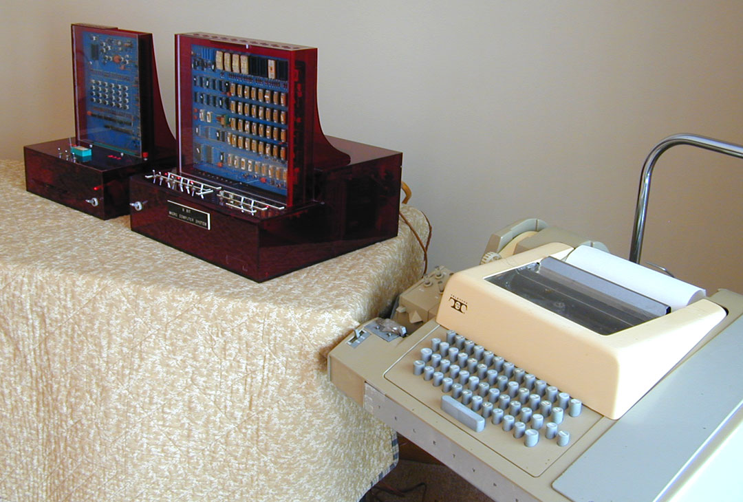
A few years ago I inquired about an early 8-bit micro in my collection that
I did not know the background on. Recently I found out the background of the
computer and thought I would share it with the history buffs here.
It was built by the Univac R&D Division in St. Paul, Minnesota in 1972. They
were carefully monitoring the developments at Intel with regard to their
4004 and 8008 microprocessors being developed. Part of their research was to
construct actual computer systems to research and then build an application
using the 8008. They started by building a 4-bit system similar to the one I
have using the SIM4-01 and MP7-01 boards. That unit was completed and being
demonstrated by March of 1972. They ordered the 8-bit system (SIM8-01 and
MP7-02) when it was announced in April of 1972 and construction took place
during the summer of 1972. Univac designed and built their own interfaces
for these systems and used a Teletype for I/O. The Univac 8008 "8-Bit Micro
Computer System" in my collection was complete and being demonstrated to
various Univac divisions and military organizations by early fall of 1972.
I visited with one of the Univac engineers that did some of the programming
and he said that only very simple programs were used in demonstrations--like
doing simple math operations or it asked for your name, you typed it in on
the teletype and it printed some phrase using your name.
Univac spared no expense in developing this system as seen in the
construction and fabrication of the cases which are thick, deep red
translucent plastic. Not only is it a very aesthetically designed, but it
has to be one of the very first 8-bit computers fully assembled and
operational.
Here is a photo of the system:
http://solomonson.net/computers/Univac.8008.TTY.jpg
I have also done a You Tube video telling more about the system:
https://www.youtube.com/watch?v=9KojS1ezQIY
Hi all,
anybody in Denver Area looking for some?
I have two I don't need anymore, and for a small fee, you can pick em up.
Sorry, no shipping, no accessories ...
Esteemed listmembers;
I have started working on restoring a 3B2/300, and right away I've discovered the probable cause for the machine's catatonic state. Three of the system board EPROMs are missing.
Anybody got a /300 they can dump the EPROMs on? For some reason the AATKL ROM (3/4) is still fitted, so technically speaking I only need images of the AATKJ (1/4), AATKK (2/4), and AATKM (4/4) EPROMs.
I may also be after a copy of the AARAM (2/2) ROM from the NI (ethernet) board. My EPROM programmer can't get a good connection on pin 1 of that device and reads it as all zeros. It may still be okay in the socket on the board.
ok
bear.
--
until further notice
We did more debugging on the PDP-8/I today. The individual CLA and CMA
instructions work OK, but the combined CLA CMA instruction does not set all
of the AC bits to 1s. Tracing with a 'scope found that the AC ENABLE signal
was not active during the combined CLA CMA instruction. Replacing the M160
in slot E30 fixed the missing AC ENABLE signals and fixed the combined CLA
CMA instruction. The Instruction Test 1 and Instruction Test 2 diagnostics
ran OK, so the processor is probably working fine. The TC01 DECtape diags
did not run as expected so we need to read the manual before we try it
again next week
--
Michael Thompson
I ordered a couple XT-CF-Lite boards as described in
http://www.malinov.com/Home/sergeys-projects/xt-cf-lite. Has anyone else
here built and used this? I have a problem with the BIOS. Either Sergey
specified the wrong size EEPROM or provided the wrong BIOS image. The
specified EEPROM holds 8192 bytes while the BIOS image is 32,768 bytes.
I sent an email to Sergey, but I thought I'd ask here too.
--
David Griffith
dgriffi at cs.csubak.edu
A: Because it fouls the order in which people normally read text.
Q: Why is top-posting such a bad thing?
A: Top-posting.
Q: What is the most annoying thing in e-mail?