On 2015-Mar-16, at 7:20 AM, John Foust wrote:
> I'm trying to understand at a low level how some early computers
> and game consoles generated a non-standard form of NTSC.
>
> The Wikipedia http://en.wikipedia.org/wiki/Low-definition_television says:
>
> "Older video game consoles and home computers generated a nonstandard NTSC
> or PAL signal which sent a single field type which prevented fields from
> interlacing. This is equivalent to 240p and 288p respectively, and was
> used due to requiring less resources and producing a progressive
> and stable signal."
>
> Another source says this was true for the "NTSC Atari 2600, Apple II
> family, Commodore 64, Nintendo Entertainment System, Sega Master
> System, and the vast majority of games for NTSC Genesis, Super NES,
> PlayStation, and Nintendo 64."
>
> This page http://www.hdretrovision.com/240p/ calls it a "special timing
> signal" and gives examples of how contemporary flat-panel TVs can
> misinterpret the old signal. The issue has spawned the creation of
> dozen of devices to give the retro look on new TVs.
If you're just referring to the interlaced vs. 'progressive' scan issue, it comes down to the relationship between the vertical and horizontal scan rates.
The standard RS-170/NTSC sync-pulse frequencies of V=60Hz and H=15,750Hz [*], give an H/V ratio of 262.5, which of course is the number of lines which will be scanned during the vertical scan period. The half fraction results in the vertical sync ' interrupting' the last line of half the scan fields half way through the line and the first line of the other half of the fields starting halfway through the line so the fields are vertically offset slightly and thus interlaced.
(Multiplying 262.5 by 2 gives the proper 525 NTSC lines per frame (and of course notice it's an odd number)).
When ones looks at the V and H sync pulses in relation to each other, they are alternating/oscillating in relative phase to each other.
In the properly-implemented standard, that alternating phase relationship necessitated equalizing pulses in the signal at twice the H rate around the V sync/retrace period to keep the old analog-implemented sync-separators happy.
If the H/V ratio is adjusted slightly off the standard to an integral relation, for example by setting the H scan rate to 15,720Hz to give 262 (lines), the H & V sync pulses are always in the same phase relationship, and there's no interlacing.
The altered scan rates were still within the sync-lock range of the analog TVs of the day, perhaps needing a slight tweaking of the horizontal-hold control.
I was trying to find what the -exact- frequencies are for some of those early computer/game systems but nobody seems to want to readily present them on the interwebs.
[*] In NTSC, the rates were adjusted slightly from the original B&W spec with the introduction of colour, to, 59.94 & 15,734; IIRC, to deal with the colour information in the signal displaying artifacts when displayed on existing B&W TVs.
Ok,
I will scan in this way...
I just ordered an used semi-pro HP scanner with front/back ADF... I hope
it will arrive sooner.
In the end, when the documents will be ready, I will but them on dropbox.
Whom should I send the link then?
Andrea
The VCFMW hotel room group rate is active! Follow the Holiday Inn
link under "location" on the main vcfmw.org page or mention "vintage
computer festival" or group code "CCC" when calling 1 (877) 834-3613.
The rate is $84/night, only $5 more than last year for a finer venue.
That rate covers either the single-King or double-double "executive"
room, which means you get a microwave and mini-fridge for your
leftovers.
The block is held until 8/7, so there is plenty of time yet if you're
not sure you can make it. But if you are, book soon so we have an
idea of how many are coming and whether we need to expand the block.
See you in August!
> From: Eric Smith
> The power draw of the 11/45 and 11/70 is almost the same, with the
> exception of the separate memory box(es)
Well, the 11/70 does have the cache, the UNIBUS map, etc that the 11/45 does
not. I forget how many extra cards that all works out to, but my vague memory
is that it's roughly half a dozen.
Noel
Hi,
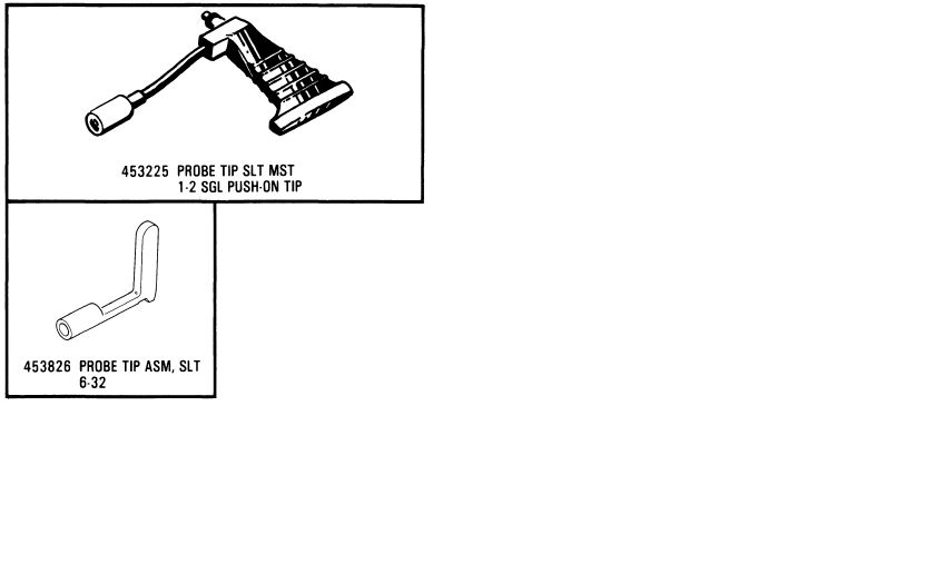
Who can help me with a source (not IBM) for logic probe tips
used with IBM MST and SLT backplanes.
See: http://home.hccnet.nl/h.j.stegeman/IBM_logic_probes.jpg
Prefably the lower one (P/N 453826).
Thanks for your replies.
Regards Henk
>Glen Slick wrote:
>>On Mon, Feb 16, 2015 at 11:47 AM, Noel Chiappa <jnc at mercury.lcs.mit.edu> wrote:
>
>
>>This may be common knowledge here, but I was unaware of it (and, AFAIK, the
>>DEC documentation doesn't point this out), so here goes...
>>
>>It turns out one doesn't need the fancy cab-kit to connect up to an 11/23+'s
>>console. The headers on the card are completely compatible with standard
>>DLV11-J connectors, and a DLV11-J cable can be used to connect up to an
>>11/23+ card. (One has to select the desired baud rate with the DIP switches
>>on the card, of course.) I have verified this by trying it, and it worked.
>>
>>The cabkits merely allow one to select the baud rate at the console connector
>>(via a clock generator on the cabkit, and the 'external clock' input on the
>>serial interface). This implies that one should be able to plug a cabkit into
>>an appropriately configured DLV11-J (external serial clock select), and
>>select the baud rate via the switch on the cabkit. I haven't tried that,
>>though.
>>
>If anyone is looking for the real cabkit for the M8189 PDP-11/23+ JT
>Computer currently has some listed on eBay for $45. There were 5
>listed, 2 sold last week:
>
>http://www.ebay.com/itm/151615474481
>CK-KDF11-BA M8189 CABKIT INCLUDES PANEL AND CABLES
>
>I finally got around to buying a CK-KDJ11-D cabkit for the M7554
>KDJ11-D directly from their website ( www.jtcomputer.com ) a week ago.
>I've had good results buying a few things from them.
>
Check
John Foust <jfoust at threedee.com> wrote:
> I'm trying to understand at a low level how some early computers
> and game consoles generated a non-standard form of NTSC.
>
> The Wikipedia http://en.wikipedia.org/wiki/Low-definition_television
> says: (...)
Adam Sampson <ats at offog.org> wrote:
> There's a pretty good description here, with diagrams of the video
> waveforms involved for both PAL and NTSC (both use the same idea):
> http://martin.hinner.info/vga/pal.html
>
> (...) in the kind of non-interlaced
> signal you're talking about, every frame starts with the odd field
> vertical sync, so the monitor always pulls the electron beam back to
> the same place.
A-ha, interesting to see that this sort of shortcut was actually taken
in commercial products. I pretty much accidentally ended up with that
sort of signal when I, back in 2010ish, tried to coax a Sun cg3 style
framebuffer (onboard FB of a SPARCclassic) into outputting a (50Hz) TV
displayable RGBs Signal by feeding it a hand-crafted "mode line" after
working out what the registers on the video timing ASIC do. I'm
pretty sure there will be some accounts of that adventure in the list
archive as a list member helped me through it.
I got the picture to display on my Commodore 1081 Monitor via a 13W3
to SCART cable I had fashioned therefore, but of course wasn't very
impressed with the vertical resolution, and couldn't find out how to
enable interlaced mode on the ASIC - if it's capable of that at all.
So Long,
Arno
This may be common knowledge here, but I was unaware of it (and, AFAIK, the
DEC documentation doesn't point this out), so here goes...
It turns out one doesn't need the fancy cab-kit to connect up to an 11/23+'s
console. The headers on the card are completely compatible with standard
DLV11-J connectors, and a DLV11-J cable can be used to connect up to an
11/23+ card. (One has to select the desired baud rate with the DIP switches
on the card, of course.) I have verified this by trying it, and it worked.
The cabkits merely allow one to select the baud rate at the console connector
(via a clock generator on the cabkit, and the 'external clock' input on the
serial interface). This implies that one should be able to plug a cabkit into
an appropriately configured DLV11-J (external serial clock select), and
select the baud rate via the switch on the cabkit. I haven't tried that,
though.
Noel
On Mon, Mar 16, 2015 at 8:20 AM, John Foust <jfoust at threedee.com> wrote:
> I'm trying to understand at a low level how some early computers
> and game consoles generated a non-standard form of NTSC.
There were several non-standard aspects of the Apple II "NTSC" video
signal which made it not actually NTSC-compliant. It was mostly a
matter of timing. The most significant deviations were lack of
interlace (60 frames per second, rather than 30 frames per second each
comprised of two interlaced fields), and that each horizontal scan
line was 228 color carrier cycles long rather than 227.5, which was
done so that the color carrier phase relative to horizontal timing was
the same on all scan lines. Early revisions of the Apple II were also
missing the serrations in the vertical interval.
Some people claim that the way color was generated in the Apple II was
somehow "fake" and refer to it as "artifacts" that somehow "trick" the
television or monitor, but in actuality it was just a clever way of
having the hardware produce various signal amplitudes and phases, just
as "real" color does. It was clever enough to be patented, but it's
not in any way "wrong" or "fake".
When other devices have an issue with Apple II video as a source, and
don't reproduce the colors properly, in my experience it is usually
the 228 vs. 227.5 color carrier cycles per scan line that is at fault.
In the early 1980s, Video Associate Labs sold a product for the Apple
II called the VB3 Microkeyer. This consisted of a long slot 7 card,
and a larger card that installed atop the power supply, connected by a
ribbon cable. You had to pull about a dozen chips out of the Apple II
motherboard (thus it would only work with the II and II+, but not the
IIe or IIgs), and install in their place ribbon cables to the VB3
boards. The results were:
1) The Apple II would generate fully-compliant broadcast-quality NTSC
output. (IIRC, there was a way to selectably disable interlace, which
would break NTSC compliance.)
2) proc amp and gen lock: The Apple II video could be overlayed on an
external video input. This could be done selectively (keying), and it
was also possible to do software-controlled "wipes" between two video
inputs, using the Apple video bitmap as the input selector.
3) A special "linear" high-res graphics mode was added, in which the
addressing of the frame buffer was linear rather than having the
normal Apple II interlaced addressing. This made it easier to program
keying and wipes, but could be used for other purposes.
I used and programmed one of these in the instructional television
studio of a community college. I wrote some "wipe" programs for it,
and licensed them to Video Associate Labs in exchange for a VB3 of my
own. Alas, I no longer have it. :-(
Years later Apple introduced a Video Overlay card, which did produce
broadcast-quality NTSC output, and would work in the II, II+, IIe, and
IIgs. It supported all of the IIgs graphics modes, even when used in
an earlier model computer.