Message: 18
> Date: Thu, 6 May 2021 15:18:04 +0200
> From: Liam Proven <lproven at gmail.com>
> To: Jay Jaeger <cube1 at charter.net>, "General Discussion: On-Topic and
> Off-Topic Posts" <cctalk at classiccmp.org>
> Subject: Re: That VAXStation4000vlc 3W3 video connector
> Message-ID:
> <
> CAMTenCGKYnC++cT2gfpCvvntTjv-FrvivhuoXLcjWDesf2WC9w at mail.gmail.com>
> Content-Type: text/plain; charset="UTF-8"
>
> On Wed, 5 May 2021 at 17:59, Jay Jaeger via cctalk
> <cctalk at classiccmp.org> wrote:
>
> > I, for one, did find this helpful - one could make one of these up to
> > test before possibly forking over the funds to build one properly.
>
> If anyone were up to making a small batch of these, I'd be happy to
> pay for a few, plus shipping etc. I have 3 ? 4000VLCs and only 1
> monitor for 'em, and I hope to get them running again sometime...
>
>
>
I'd buy at least one, seeing as how it was my original question, and
whatever I end up stitching together will be really gross.
If whoever is doing it would ALSO do the much simpler DEC 15-pin to VGA
adapter, I'd probably buy some of those too.
Adam
> On 4 May 2021, at 19:00, cctalk-request at classiccmp.org wrote:
>
> Message: 17
> Date: Mon, 3 May 2021 16:22:45 -0700
> From: Adam Thornton <athornton at gmail.com>
> To: "General Discussion: On-Topic Posts" <cctech at classiccmp.org>
> Subject: That VAXStation4000vlc 3W3 video connector
> Message-ID:
> <CAP2nic2zsyqsLo1dFTTPh4WFV6utS1Tt_4RMsROjsmw78+8zKQ at mail.gmail.com>
> Content-Type: text/plain; charset="UTF-8"
>
> I assume it would be way too much to hope that HD BNC would fit it? Does
> anyone have a pointer to the actual physical dimensions of the itty-bitty
> BNC-ish connector in the video port of the VAXStation4000vlc? If I can get
> red, green, and blue out (assuming since there are only 3 connectors it's
> sync-on-green) I can put together a sync splitter and turn it into VGA. I
> have at least one decent multisync VGA monitor still, although none with
> the RGB BNC inputs.
Firstly, apologies if my response doesn't show up nicely in this thread --- I only receive the daily digests so I'm not sure how best to reply to a specific post...
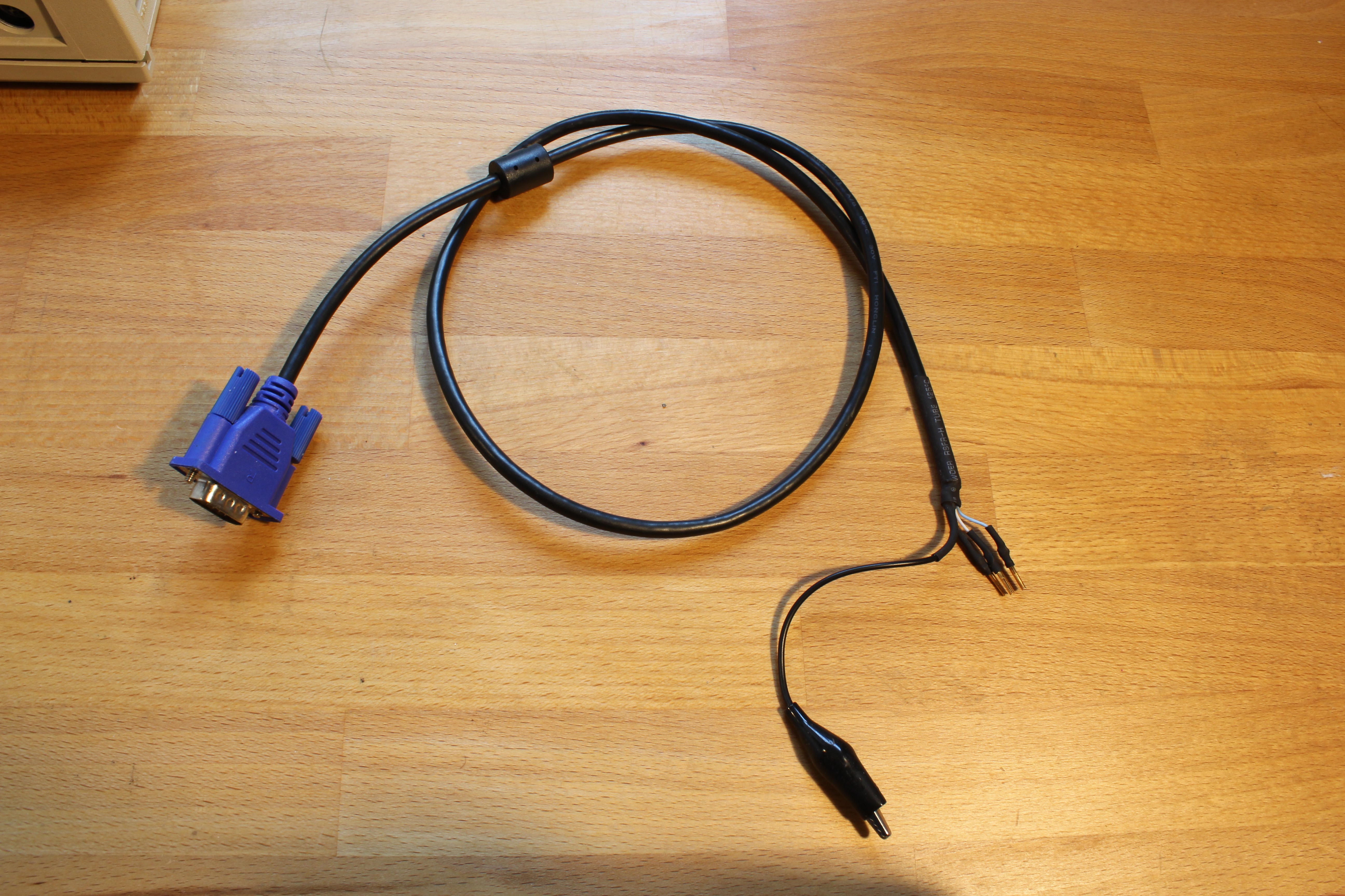
But on the subject of sourcing / making video cables with 3W3 connectors on one end, I also balked at the cost of the coaxial insets and decided to make an only marginally dodgy (if I do say so myself) cable out of half of an old VGA cable, three of the 'sleeves' / female connectors contained, in abundance, in every female D-sub connector, and a few bits of heat-shrink (see https://media.decarchive.org/DEC/VAX/VAXstation%204000-VLC/IMG_3941.jpg for a photo of this cable from an albeit sub-optimal angle). The resulting connections were surprisingly stable, however, were I to make another one, I'd replace the grounding alligator clip with a lug that can be screwed onto one of retaining nuts next to the VLC's 3W3 connector, and use longer bits of heat-shrink to fully insulate the outside of the RGB connectors...
And just FYI, even as shown, the video quality was more than adequate (considering the resolution of the VLC's LCG framebuffer), however, I suppose one could always attach a shielded DA15 shell to provide a bit of extra noise suppression (as well as mechanical protection).
Hope this helps,
Peter
>
> Date: Wed, 5 May 2021 00:03:05 -0700
> From: Josh Dersch <derschjo at gmail.com>
> Subject: PDP-8/I Negative-bus termination
>
> Hey all --
>
> Until this point I've never had any peripherals for my negibus systems
> (apart from teletypes), and it occurs to me that I have no idea if the bus
> needs to be terminated (and if so, with what). There are 6 slots in the
> RF08 backplane (D01-D06) for daisy-chaining to the next device, which is
> where I assume they'd go; the RF08 manual does not make it clear what this
> looks like or if it's actually required, and I've gone through the
> available PDP-8/I docs and I'm still at a loss.
>
> Can anyone with negibus experience point me in the right direction?
>
> Thanks,
> Josh
>
The DEC Field Service Technical Manual has some notes on bus termination.
It says:
Termination is required on I/O cables longer than 20 ft., and may be
desirable on shorter cables. For negative bus, use 220 Ohm shunt resistors
to ground on IOP 1, IOP 2, IOP 4, BTS 1, BTS 3 and Initialize. No special
termination module exists for the negative bus.
--
Michael Thompson
>
> Date: Wed, 5 May 2021 13:20:59 +0100
> From: <dave.g4ugm at gmail.com>
> Subject: RE: Motor generator
>
> We had a Motor/Generator for our Honeywell L66. Not sure it was because it
> wanted US voltages or just for a clean supply
> Dave
>
I also worked on a Honeywell L66 that had two motor-generators. We used one
at a time, and swapped the operational one each month. They cleaned up the
noise in the incoming 208VAC 3-phase power, and the really heavy flywheel
provided a little ride through for short term power drop outs.
--
Michael Thompson
..not to forget, that the 400Hz equipment was readily available
from powering aircraft on the ground before the engines take
over. So although not cheap, they where cheaper than a custom
design at an arbitrary new frequency
> Incidentally, a way to get three phase power at a frequency of your
> choice is to use a "variable frequency drive".
Please be careful with this! Have quite some experience in building
three phase inverters from such small boxes for my various avionics
projects.
(1) The normal ones rectify the mains voltage (in EU this gives
around 320V DC) and from this make PWM outputs on three lines.
Yes, you can enter voltage and frequency (sometimes even more than
400Hz) digitally, but the outputs are ALWAYS PWM switching between
0V and 320V in the EU.
Consequence: If you rectify these outputs you will get back your 320V,
completely independent of your settings!
You need to use a device called Sinus-Filter, i.e. a low pass using
caps and Ls to smooth out and get rid of the PWM - only than you
get the correct three phase.
(2) The small boxes are only for motors (inductive loads). Connecting
someting else (does not matter whether three phase or not) which e.g.
has got EMC filters at the input containing caps, the relatively high
frequency (e.g. 16kHz, often selectable) will easily toast them leading
to a short.
(3) The PWM-boxes do not isolate from mains, so you will have pretty high
voltages at the PWM outputs with high frequencies which can be a challenge
for isolations - so even if you set the inveter to 110V only, but power it
>from 240Vmains, the isolation of your device needs to handle the full
320V!
My biggest inverter based on such a small PWM motor drive inverter is
described in my blog (including schematics)...
http://www.baigar.de/TornadoComputerUnit/TimeLine.html#inverter1500
(4) DO NOT use these three phase boxes connecting one output and one
input pin to your device thinking that this is a single phase output.
Creating a "neutral" line at the output of such an inverter can be
done, but it requires additional components and than you can use
it as single phase device: Here I used a special transfomer after
the Sinus filter with input in triangle and output in star configurations.
So I get neutral PLUS insulation to mains...
Good luck!
..not to forget, that the 400Hz equipment was readily available
from powering aircraft on the ground before the engines take
over. So although not cheap, they where cheaper than a custom
design at an arbitrary new frequency
Hey all --
I cabled up the RF08 to my 8/I this evening and it's showing some very
faint signs of life -- a DIML instruction appears to do the right thing.
That's about it.
Until this point I've never had any peripherals for my negibus systems
(apart from teletypes), and it occurs to me that I have no idea if the bus
needs to be terminated (and if so, with what). There are 6 slots in the
RF08 backplane (D01-D06) for daisy-chaining to the next device, which is
where I assume they'd go; the RF08 manual does not make it clear what this
looks like or if it's actually required, and I've gone through the
available PDP-8/I docs and I'm still at a loss.
Can anyone with negibus experience point me in the right direction?
Thanks,
Josh
I'm currently reverse-engineering an AMPEX keyboard that uses capacitive key
switches. The basic design employs a GI encoder coupled to an 8039 MCU
supplemented by a 2K EPROM and 74LS373 (used to latch the ROM address set
>from Port A while Port A is then used to read data back from the ROM). The
8039 MCU drives a bit-banged serial interface. The PCB identifies itself as
AMPEX on the coper foil, although the key switch mounting-plate actually has
a "General Instruments Quality Accepted" sticker. The EPROM is labeled
"3512663-03 Copyright 1983 AMPEX CORP".
The GI encoder is a DIP-40 labeled as "321239007 M2406-054-02 GI 8233 CBU
TAIWAN". I seek technical documentation for this IC.
It evidently is not a relabeled simple variant of the documented AY-3-4592
as it does not multiplex the input side of the matrix (sense lines), there
are fewer output data lines, and the power pins are non-standard (Vcc = pin
37; GND = pin 16).
Reverse engineering identifies this M2406-054-02 as supporting an 8 column
by 16 row (3 unused in my case) matrix plus 8 output data lines. I can
identify analogs of several pins on the AY-3-4592. My interpretation of the
pin uses is that the necessary key-scanning behavior is generated using the
8039 ALE line (pin 11) as the encoder clock input.
Proper documentation for this IC would be nice to come by! Pointers and
suggestions appreciated.
Thank you,
paul


